
Menu:
2.0 Zetec-E in Mk4 Fiesta — Engine Overhaul
Contents
Removal
The donor vehicle was a 1999 Ford Cougar that had covered ~96000 miles that I bought for a mere £250. It came with a full service history but had a failed clutch slave cylinder rendering it undriveable, though the engine revved nice and smoothly. Local breakers' yards stock similar units with no ancillaries (such wiring loom, starter, alternator etc.) for around £300 so there are real benefits to buying a non-roadworthy vehicle if you have the space to store it and the tools to break it.
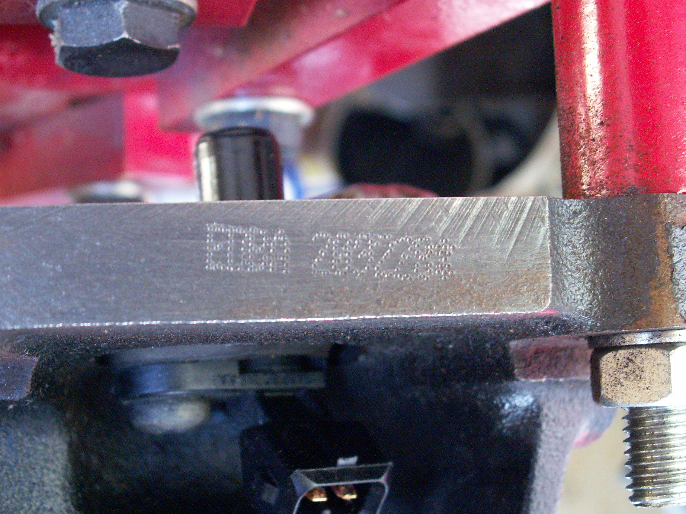
At the time I knew very little about the 2.0 Ford Zetec Engine other than that there were three variants, the Mk. 2 having an alloy cam cover and the Mk. 3 having a black plastic cam cover. The Mk. 1 and Mk. 2 2.0 engines conveniently all had the same 'NGA' engine code and were fitted to the Mondeo until 05/98 so parts were easy to find. Of the Mk. 3 engines, a number variants were made (lifted from Paul Toyne's Zetec-Cat site):
- Mondeo 2.0 (05/98 on): NGB, NGC,
- Cougar 2.0: EBBD, EBBD, EDBA, EDBB,
- Focus 2.0: EDDA to EDDG.
Spares are not all mutually compatible; the gasket sets for less common Cougar were significantly more expensive than those for the Mondeo or Cougar. The engine code is located on the exhaust side by the gearbox bellhousing, although this proved pretty elusive on the Cougar unit as it had been very lightly punched and was almost completely obscured by rust. A quick clean with a wire brush helped to reveal it.
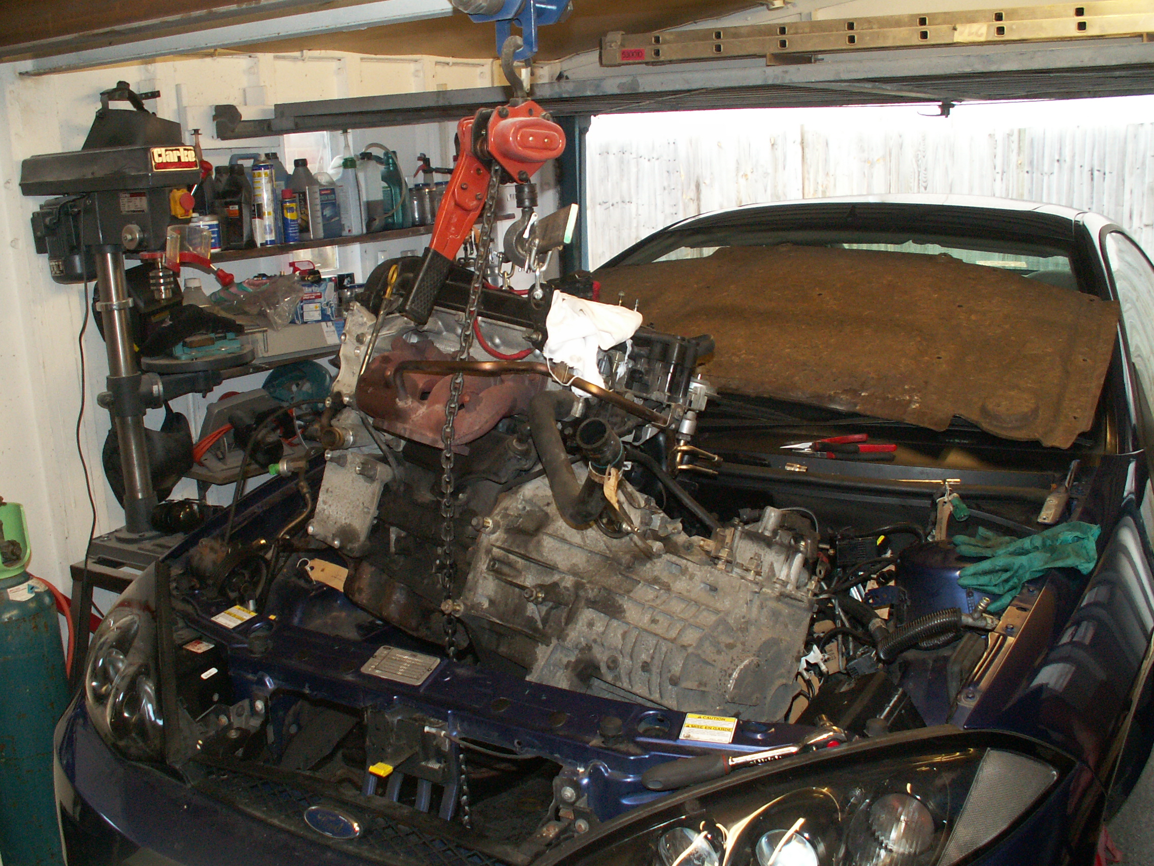
Here is the engine being removed with our home-made gantry crane. The expansion of the suspension without the weight of the engine was such that it could no longer clear the nose of the car, though we were able to bump it over without too much effort. We will remove the wheels and drop the Fiesta accordingly to ensure this doesn't happen upon refitting.
Dismantling
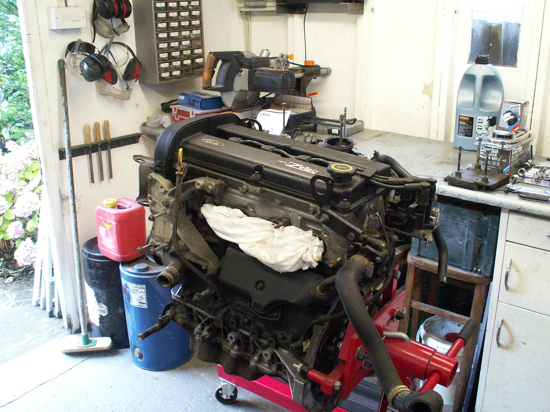
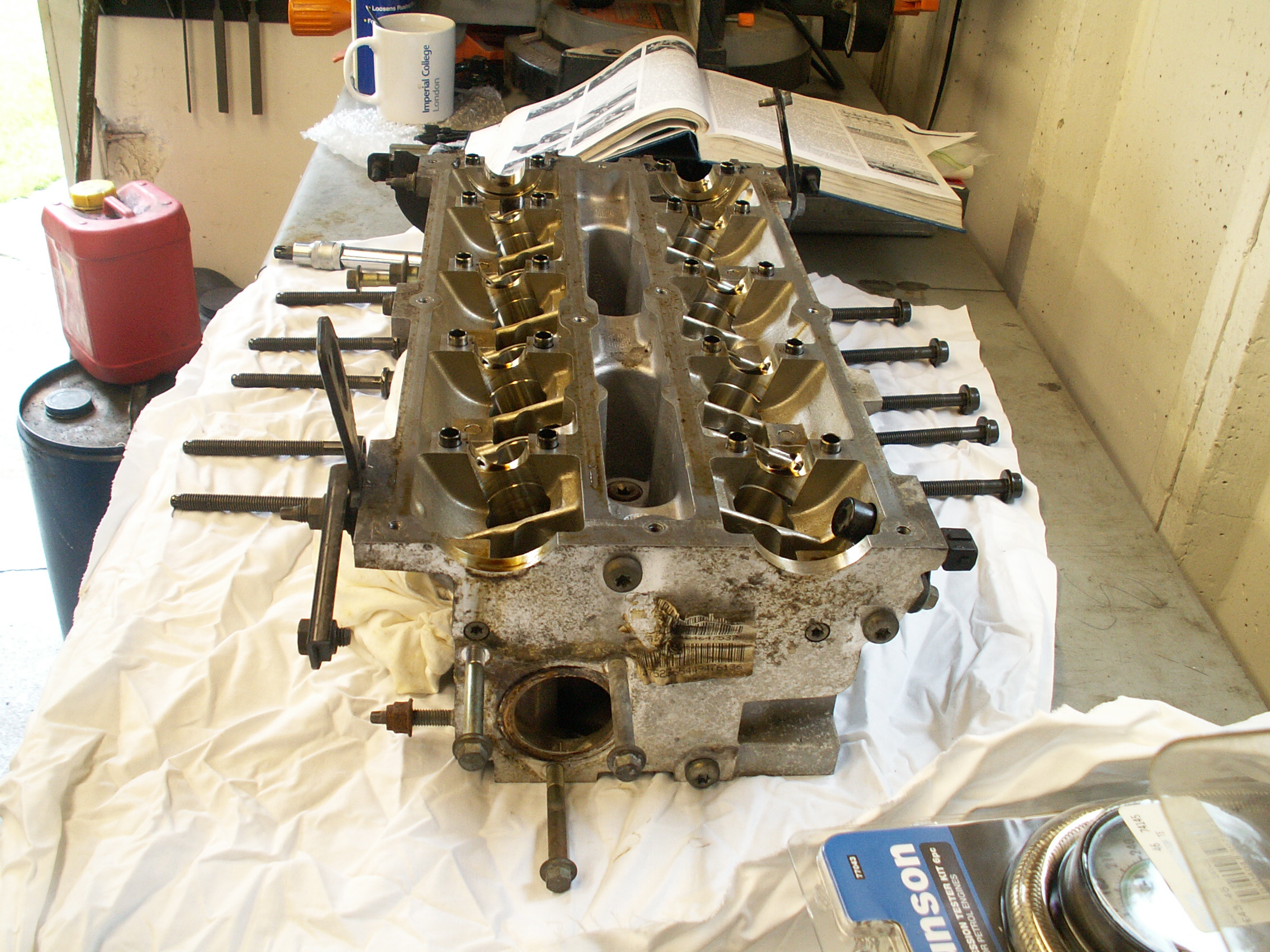
Following lifting of the engine from the engine bay, the gearbox and flywheel were removed to allow it to be bolted onto the engine stand shown below (this is a Clarke CES 750A). Most ancillary parts (including exhaust manifold, starter motor, power steering pump, air con compressor and auxiliary drive belt) were removed in order to lift the engine from the engine bay. A number of components remained before the head could be overhauled: power steering pump mounting bracket, timing belt covers, timing belt (including tensioner), distributor, alternator, alternator mounting bracket, left-hand engine mount, inlet manifold and head wiring loom.
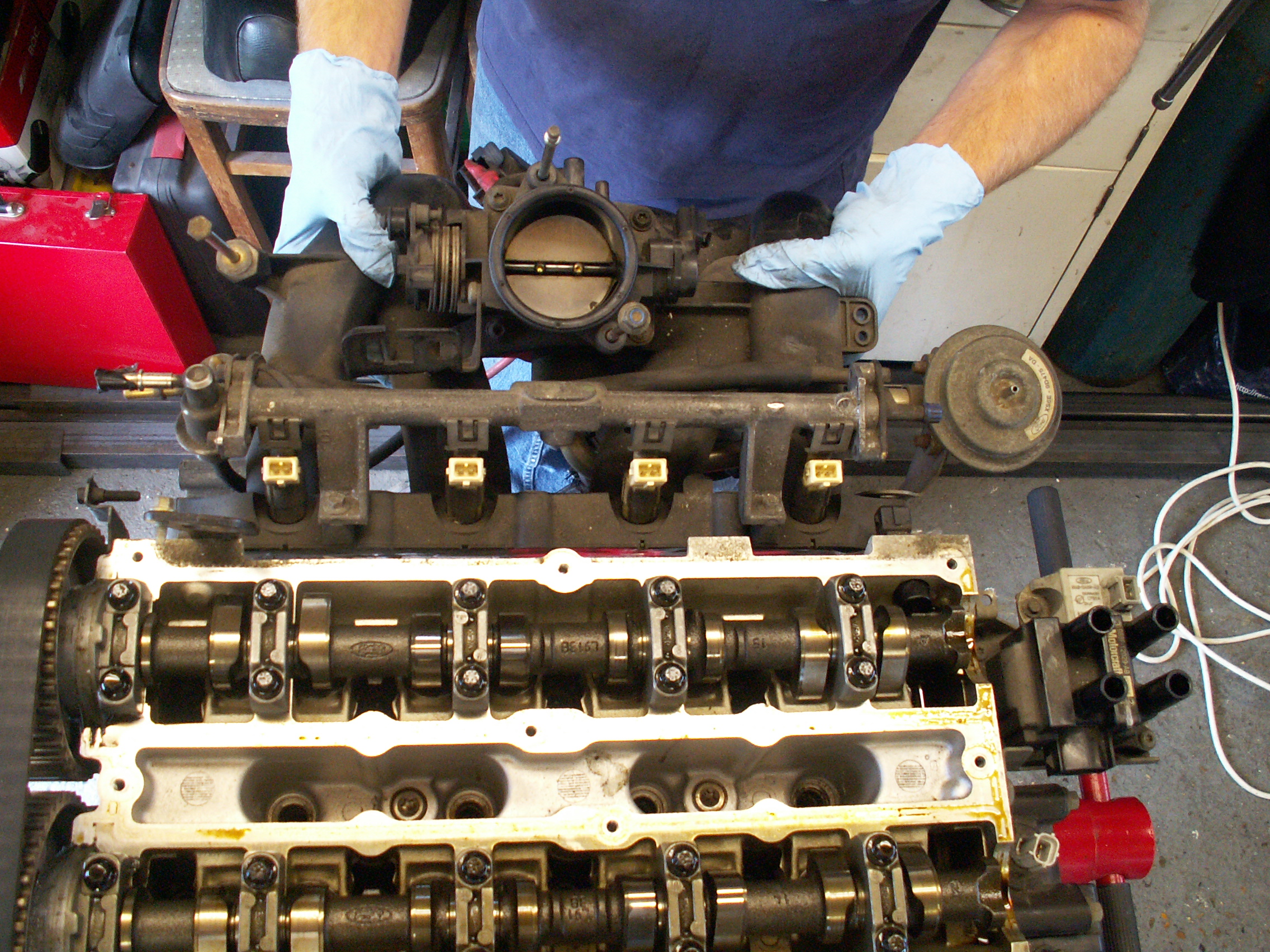
The following isn't an exhaustive list of components to be removed but gives an idea of the process. Here the rocker cover and timing belt cover have been removed...
...and here the inlet manifold.
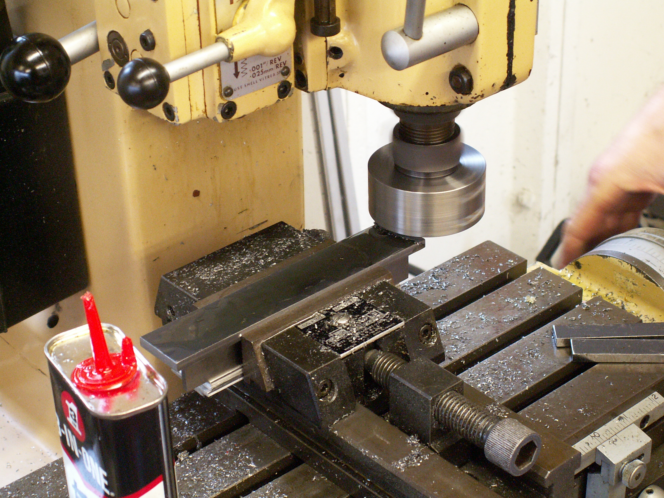
Before removing the timing belt, the engine should be rotated using the crankshaft pulley until the No.1 and No.4 cylinders are at top dead centre (TDC) with the No.1 cylinder on the compression stroke. A timing pin can be inserted to keep the crankshaft in place. The camshafts can then be locked in position by means of a tool that fits into machined slots on the No.4 end. This requires ford tool 21-162B or 303-376 or a substitute made from a 30x180mm piece of 5mm steel; I only had 6mm available so I cut a piece to size and milled it to thickness with my home-made fly cutter.
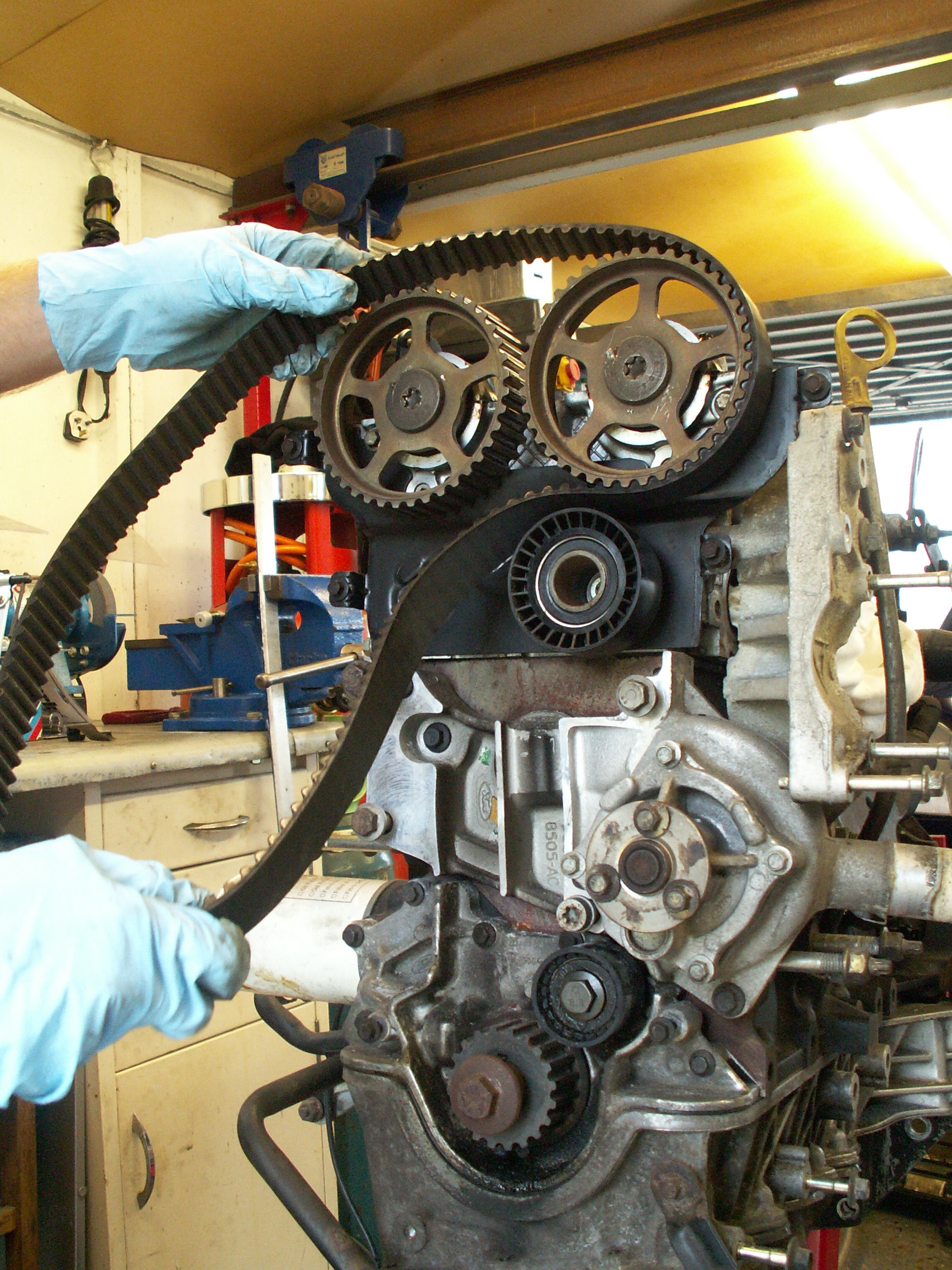
The timing belt (including covers and tensioner) can then be removed...
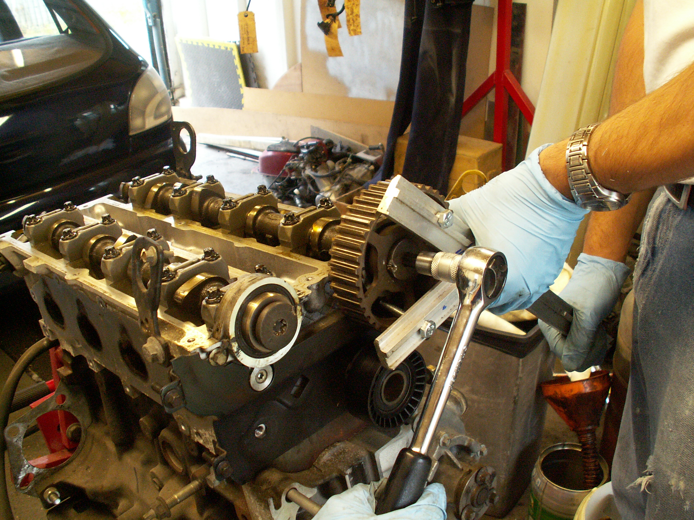
...followed by the camshaft pulley. This is a two-man job that requires fabrication of another tool to hold the pulley static while the end bolt is loosened with a TX55 Torx bit. Here we used a pair of aluminium bars joined with and a pair of bolts that locate between the spokes of the pulley. The setting bar mentioned above is not a suitable substitute for holding the pulleys as the camshafts are not designed to take the amount of torque required to loosen the bolt. Amazingly the camshaft pulleys are not splined and are held static relative to the camshaft by friction alone.
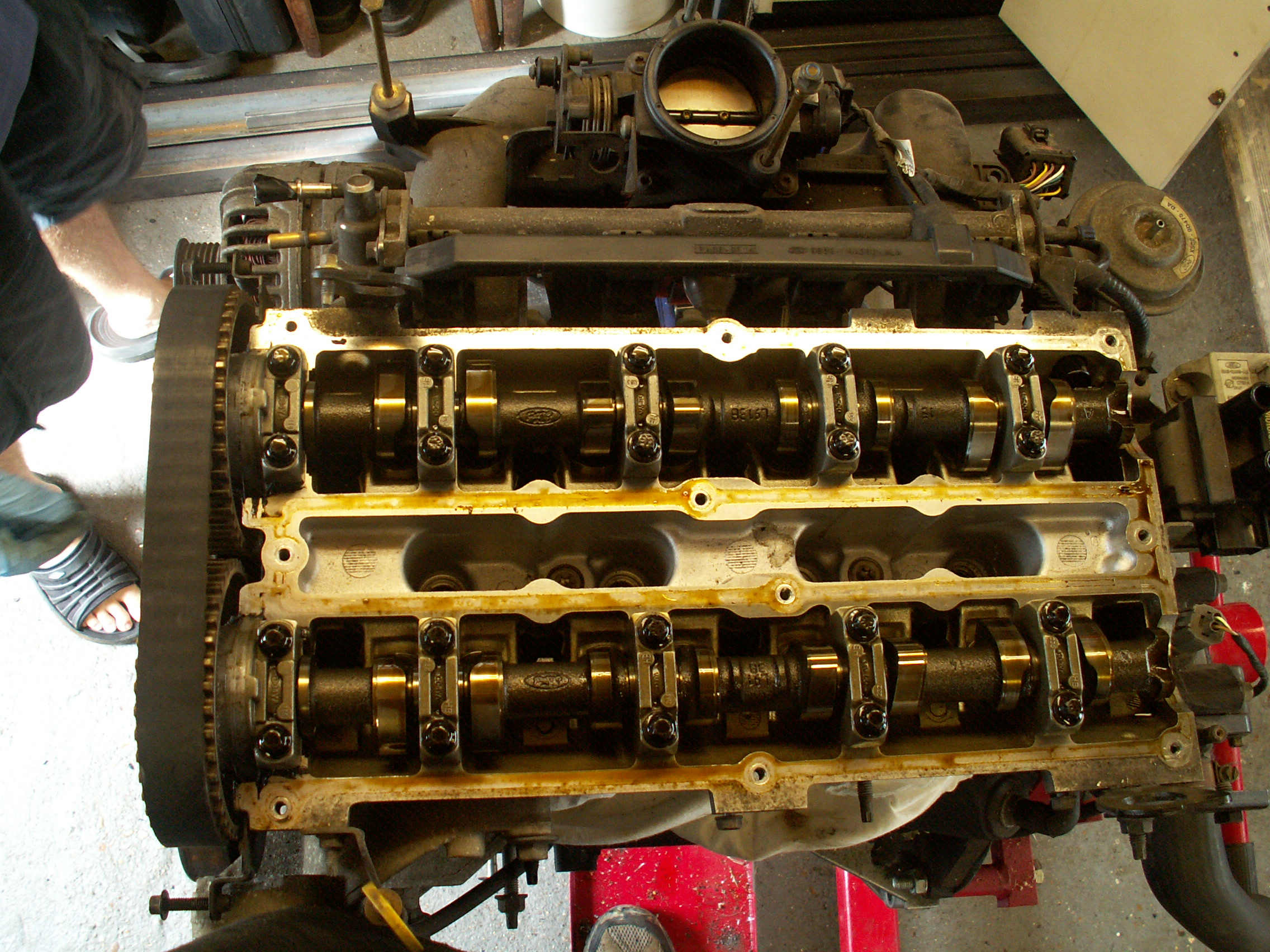
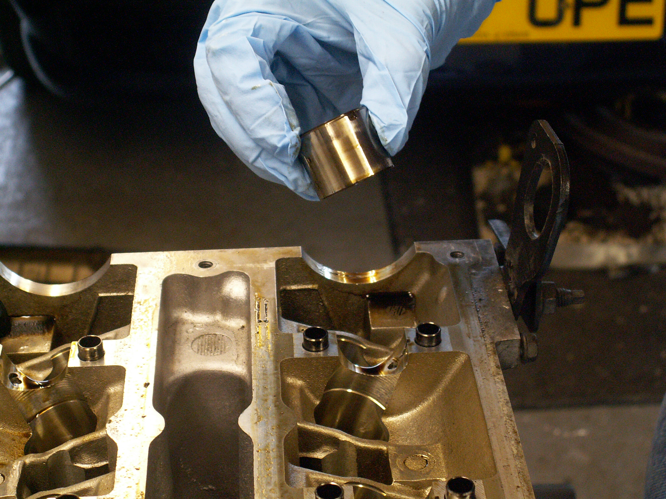
Next come the camshaft bearing caps that should be loosened in half-turn increments in the order specified by the workshop manual so as to evenly release the tension in the valve springs. Once the caps are out the camshafts can then be lifted out of position to uncover the tappets. At this point it is wise to have 16 containers that are clearly labelled to store the tappets, valve springs, split collets and valves in their correct order to avoid mixing them up which will lead to increased wear. The tappets are the first to come out; we did this by hand but a suitably-sized rubber sucker can ease removal.
This is as far as the head overhaul can go with it still attached to the engine block. The head bolts should be loosened one turn at a time in the order specified by the workshop manual, so that the head can then be removed.
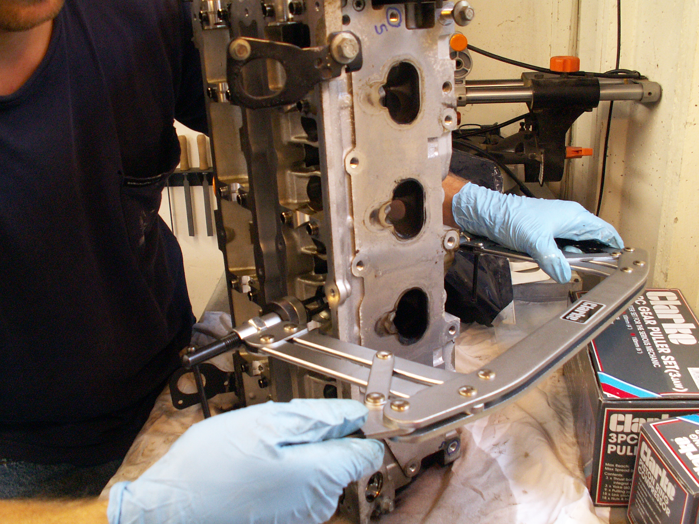
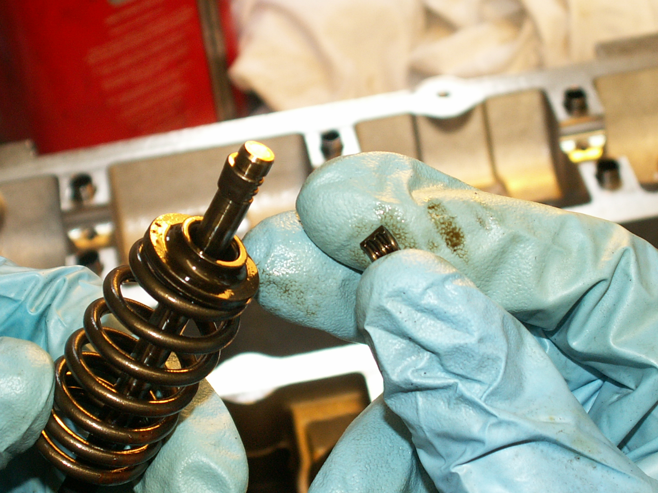
A valve spring compressor is required to release the pressure on the split collets that join the valve and the spring.
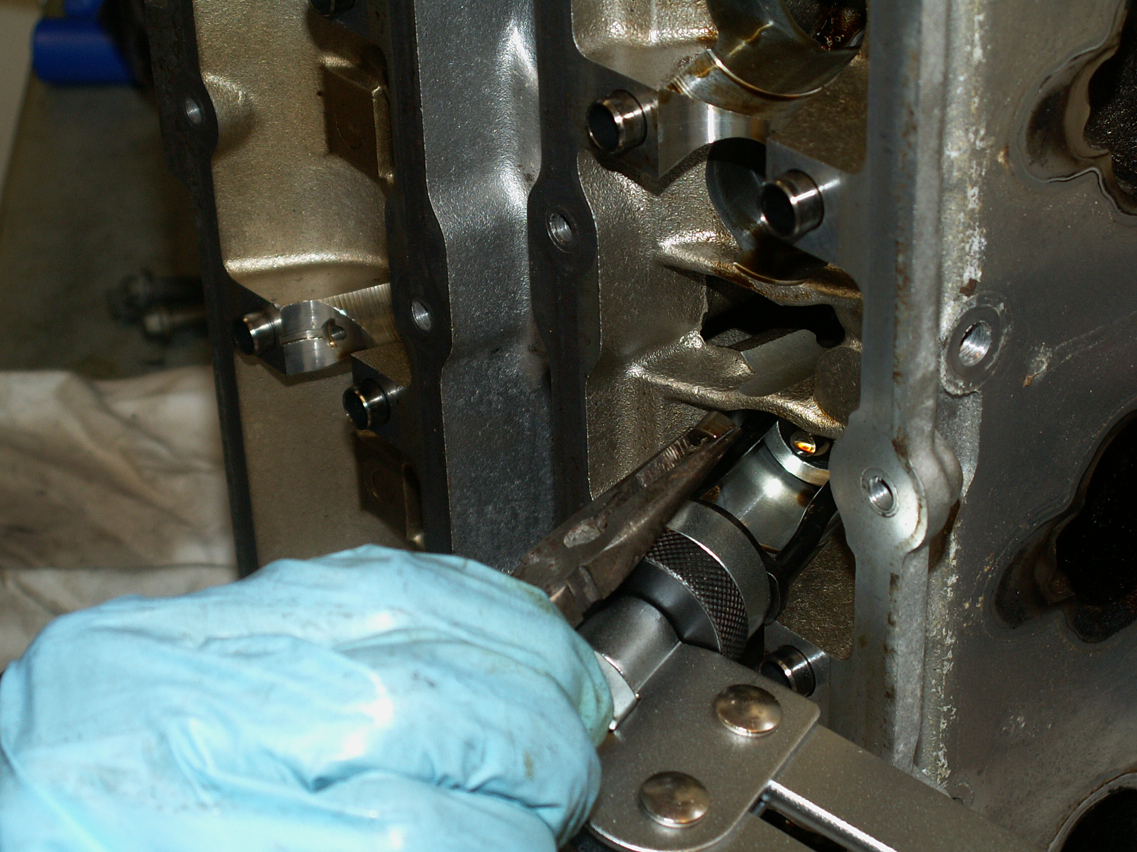
The split collets can be removed with a magnetic pickup tool or a pair of nose pliers.
The complete valve assembly consists of the valve, valve spring, spring upper seat and a pair of split collets as shown below. Each of the 16 valve assemblies are stored separately with the corresponding tappet and shim.
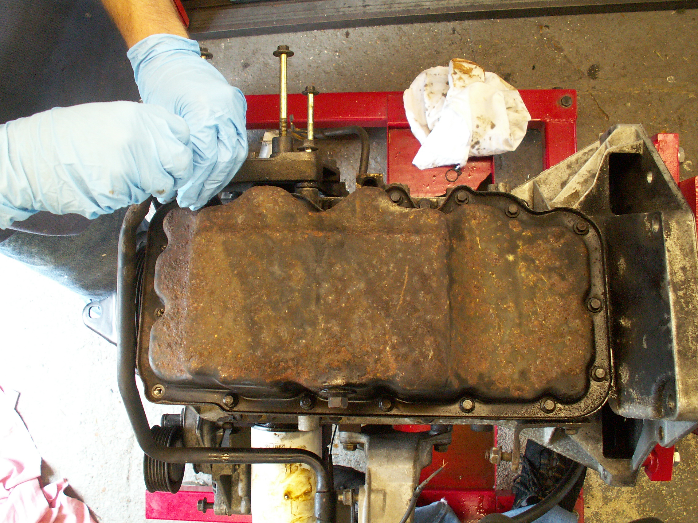
Here is a view of the oil sump (which we will clean and have powder coated):
Once removed the sump strainer can be seen which feeds into the oil pump.
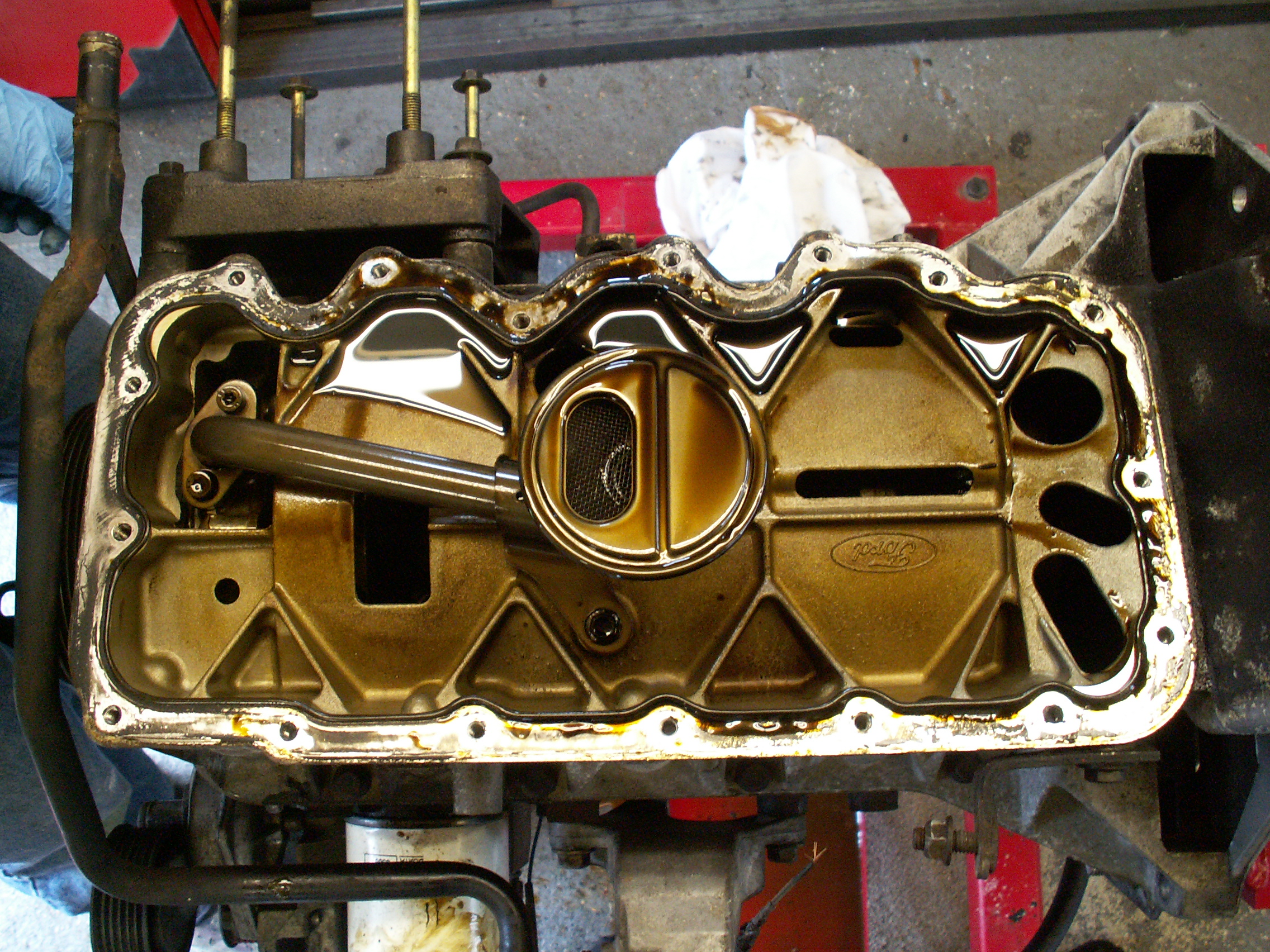
The sump strainer and lower crankcase unbolt to reveal the crankshaft and lower piston bearing caps.
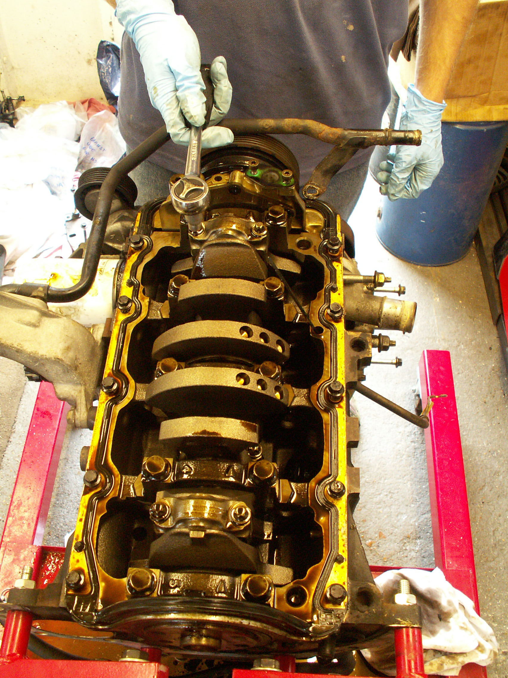
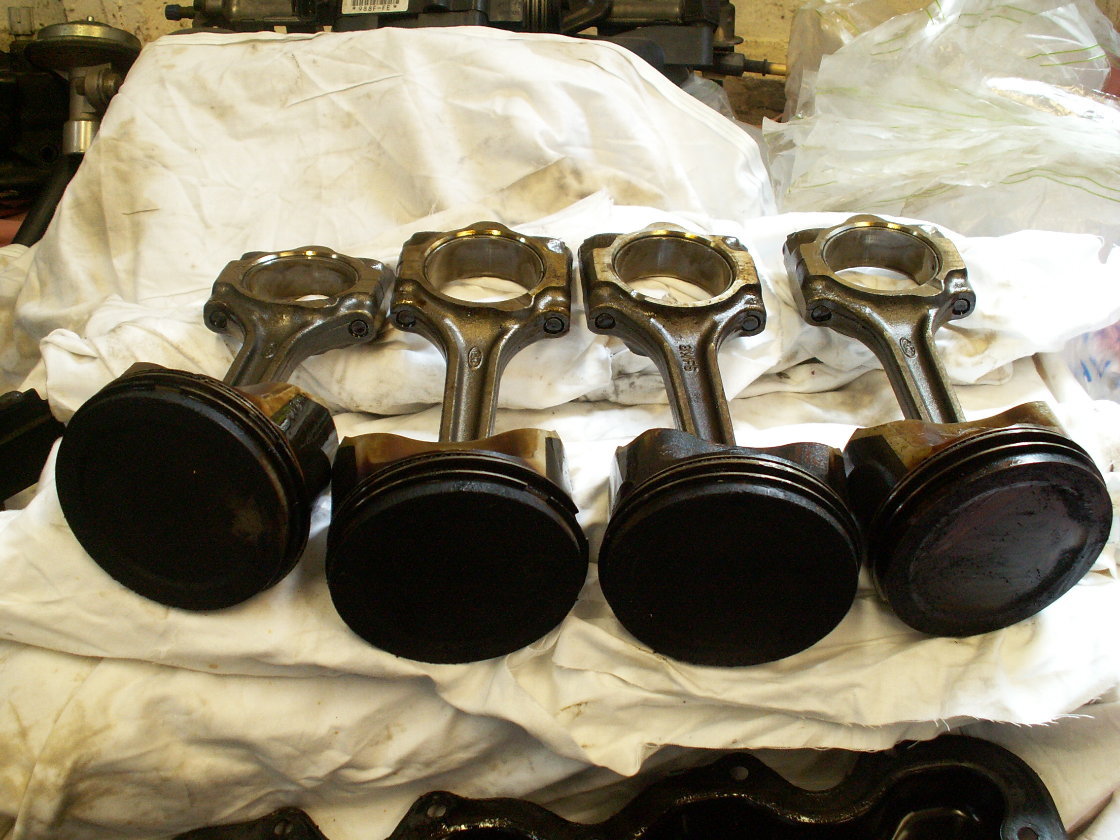
The piston should be held before the bearing cap is fully removed to prevent it falling through the cylinder. In practice the piston takes a bit of a nudge before it can be extracted. Here are the four pistons; the top of the number 1 piston (right) has had a quick scrub with a block of wood.
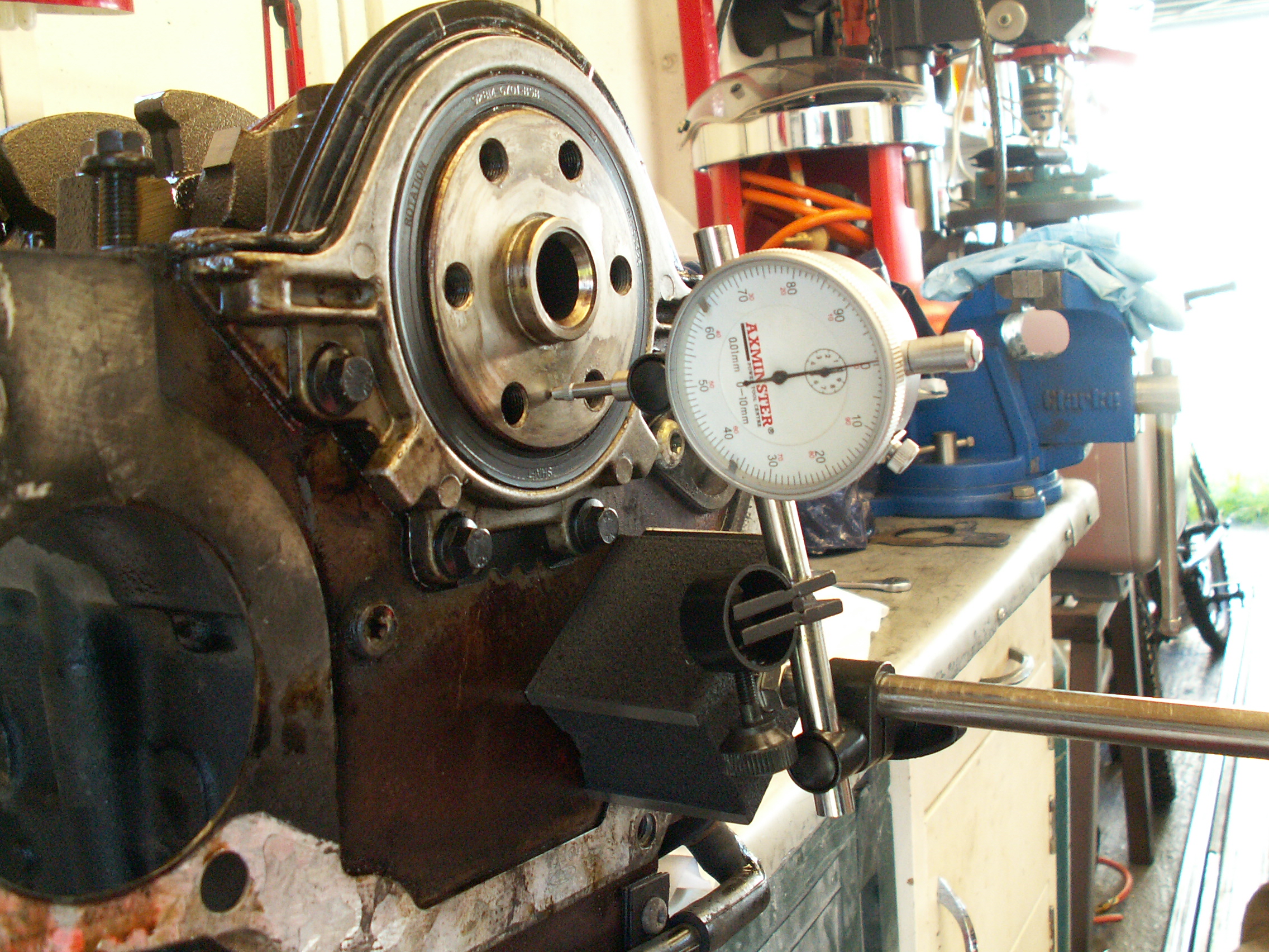
Before dismantling the block further by removing the crankshaft it is advisable to check the crankshaft endfloat. This is the freeplay of the crankshaft along the axis of rotation as measured by a dial gauge mounted on a magnetic block. If it exceeds specification then it is due to wear on the thrust surfaces or thrust washers.
The crankshaft oil seal on the flywheel end and the oil pump on the timing belt end can then be removed.
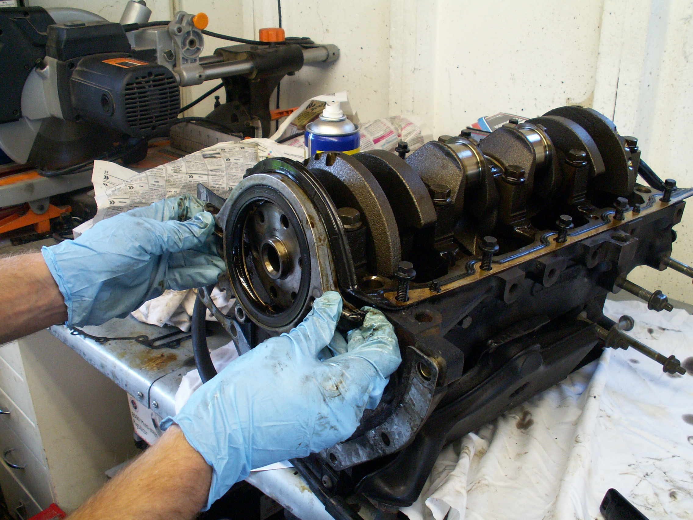
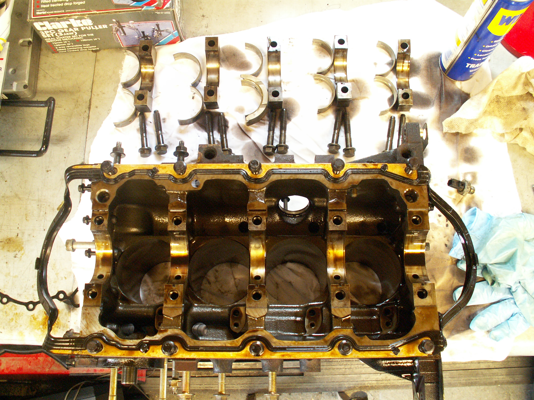
The big-end bearing caps should be embossed 1–5 from the timing belt end, each with an arrow pointing towards the timing belt. The bolts should be slackened a quarter turn at a time, working from the far ends inwards. The caps can be tapped or rocked out of place, being careful not to allow the bearing shells to fall out of the caps. Here are the block, bearing caps, bearing shells (note the thrust control bearing in the middle) and cap bolts.
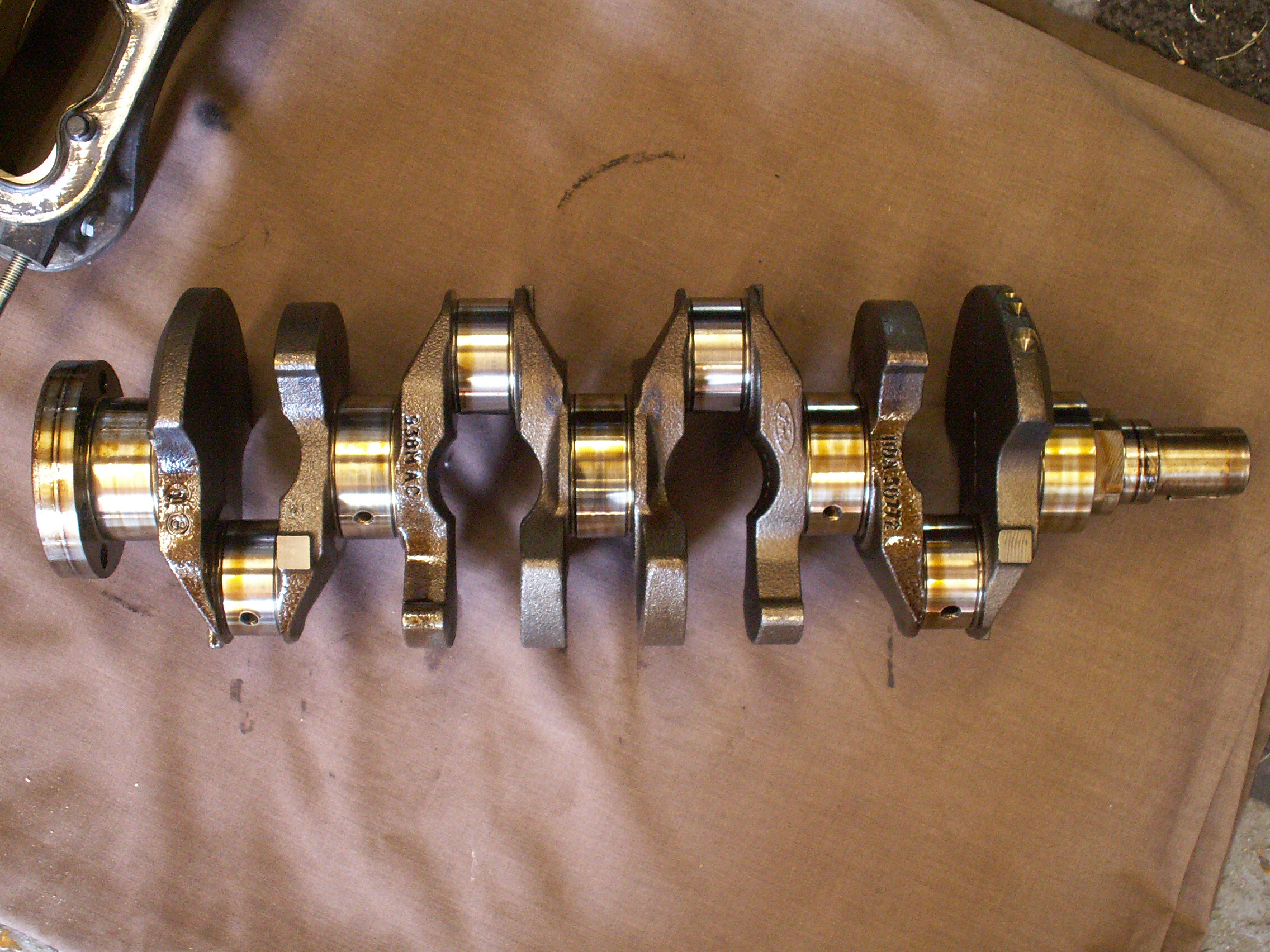
And here is the crankshaft.
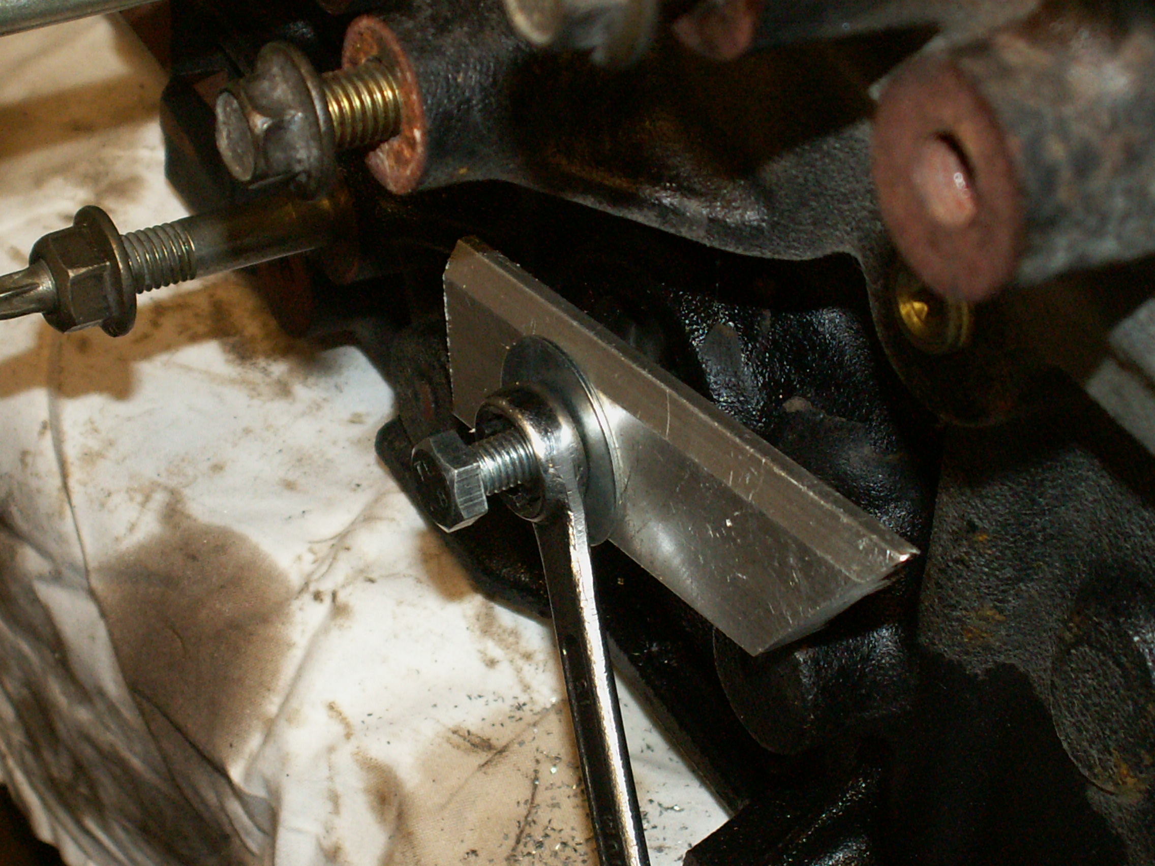
Now the crankshaft and bearing paraphernalia have been removed, all that remains on the engine block are some electrical connectors, oil jets, sump gallery plugs and core plugs. The first three are straightforward but the core plug, which is driven and bonded in place, caused some difficulty. We tried tapping the plug and pulling with a bolt as shown below but as the plug is made from thin zintec steel (I'd guess 0.7 mm) the bolt readily slipped in the tap.
Our final attempt involved making a slide hammer from box-section bracket and a rod that had been carefully MIG welded to the plug. Here is the weld:
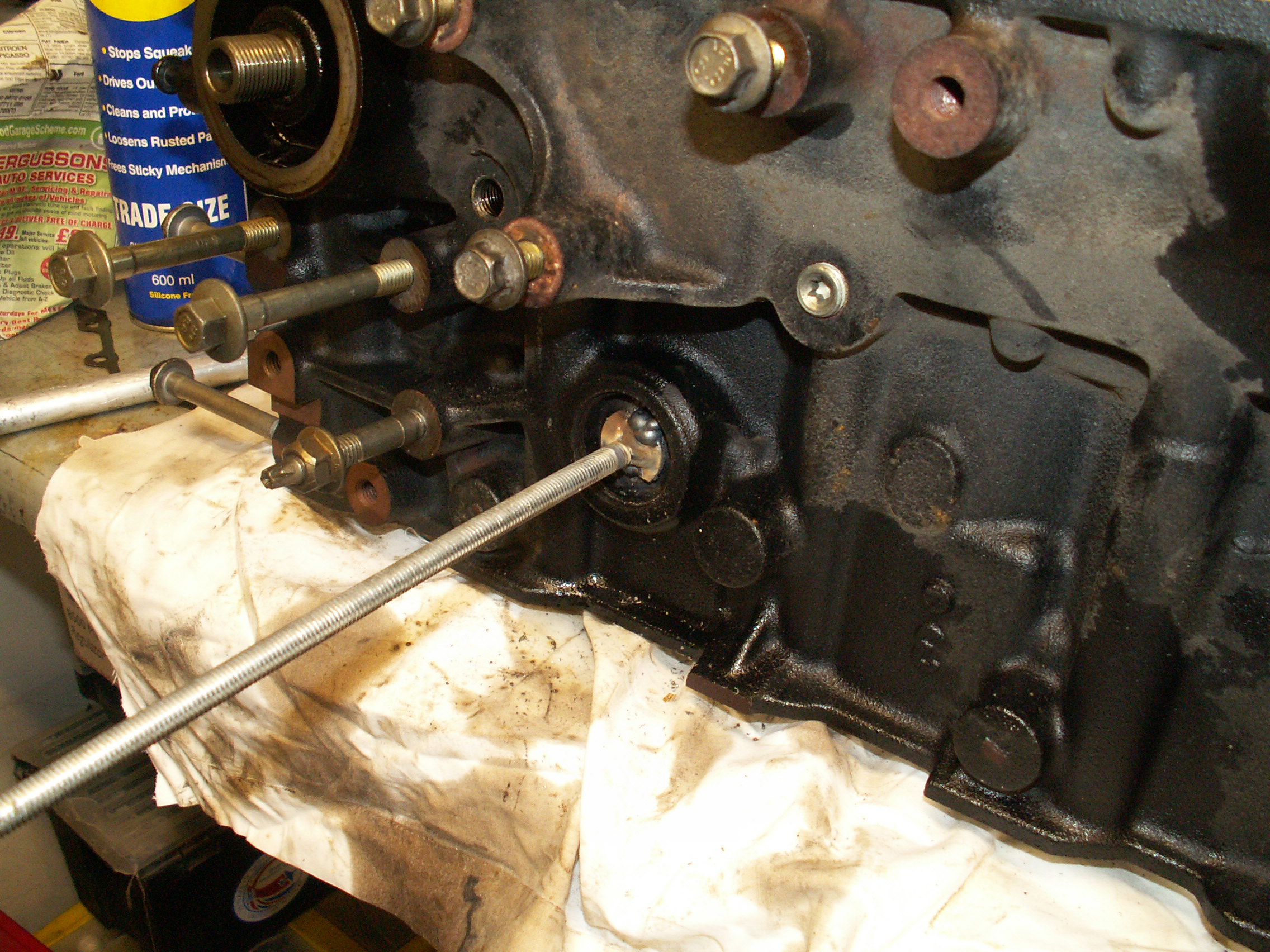
and the slide hammer:
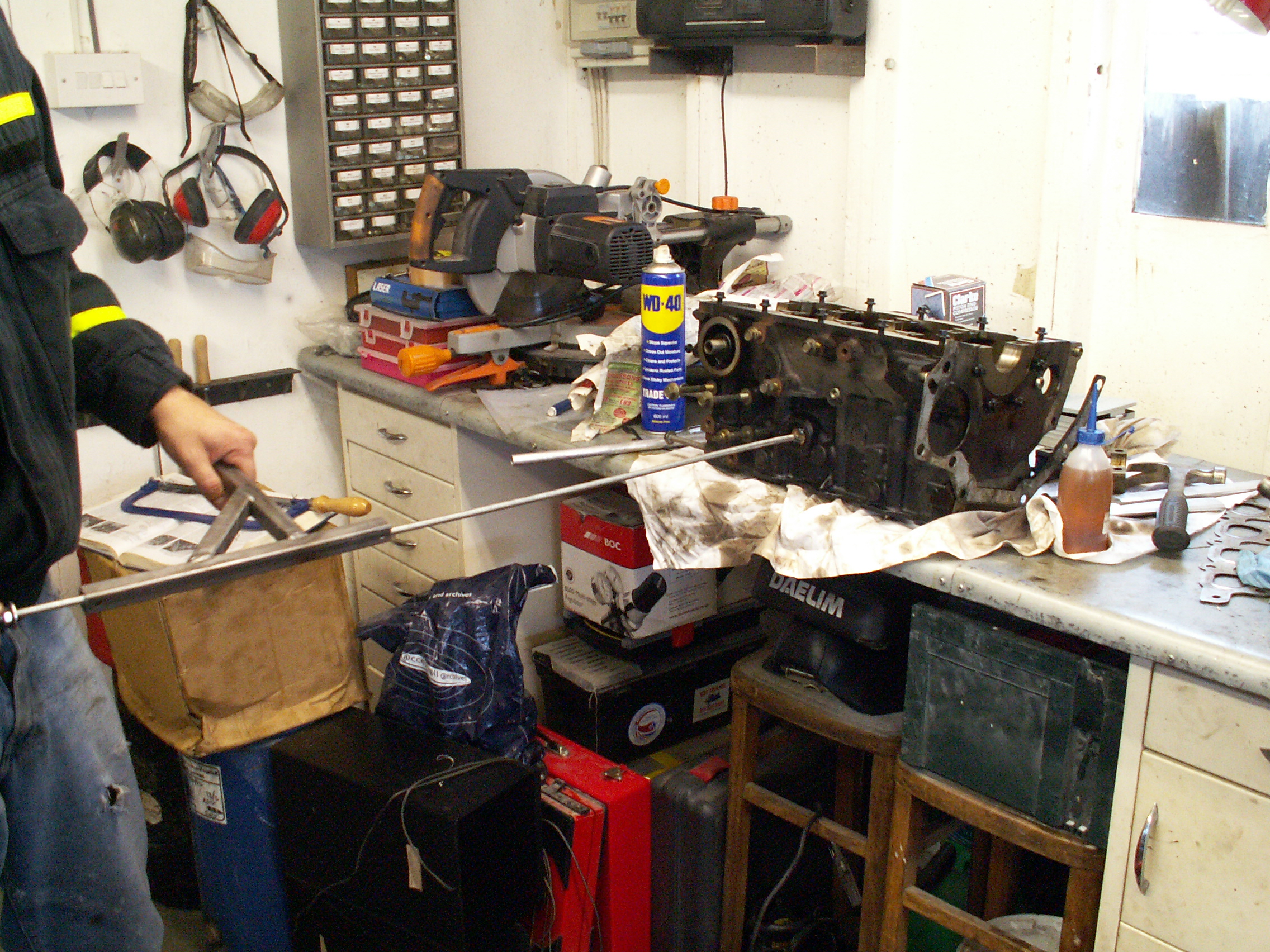
The engine is now fully dismantled and ready for restoration.

© 2010 M. R. P. Thomas