
Menu:
2.0 Zetec-E in Mk4 Fiesta — Engine Overhaul
Contents
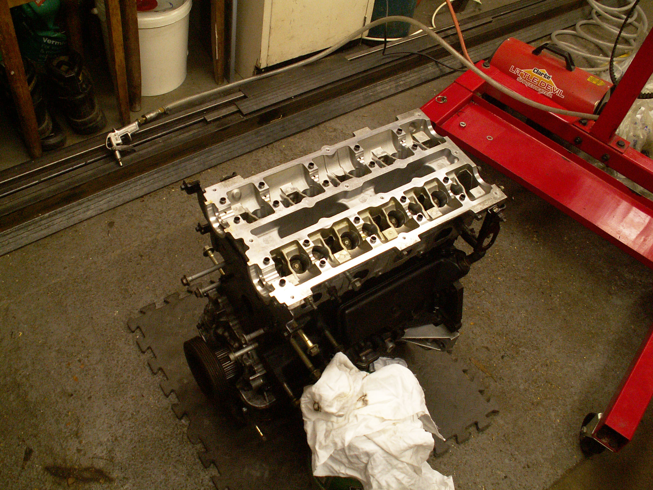
Block Rebuild
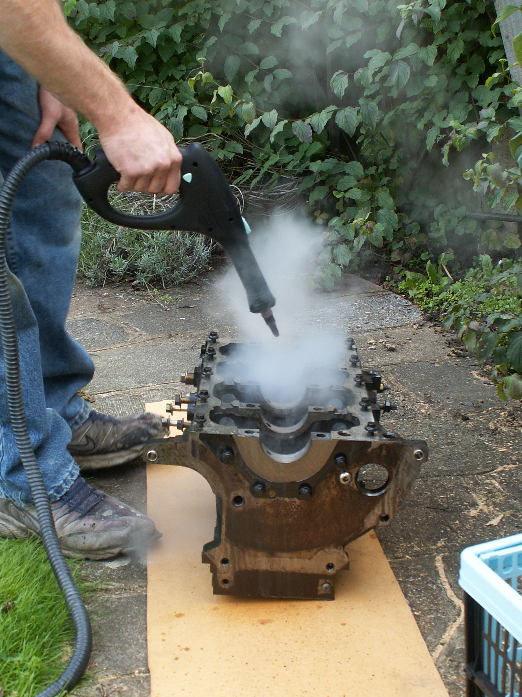
The crankshaft, bearings, studs and remaining gasket material were removed to leave the bare block ready for cleaning. A steam cleaner helped loosen solidified material, particularly in the water galleries. During the steam cleaning it was necessary to the wipe soiled water that accumulated inside. The steamer was used at a variety of different angles to ensure all dirt was removed. Compressed air helped speed drying which was followed by a generous spray of WD40 to displace any remaining water and protect it from rusting.
The threads were then cleaned and restored with the appropriate tap.
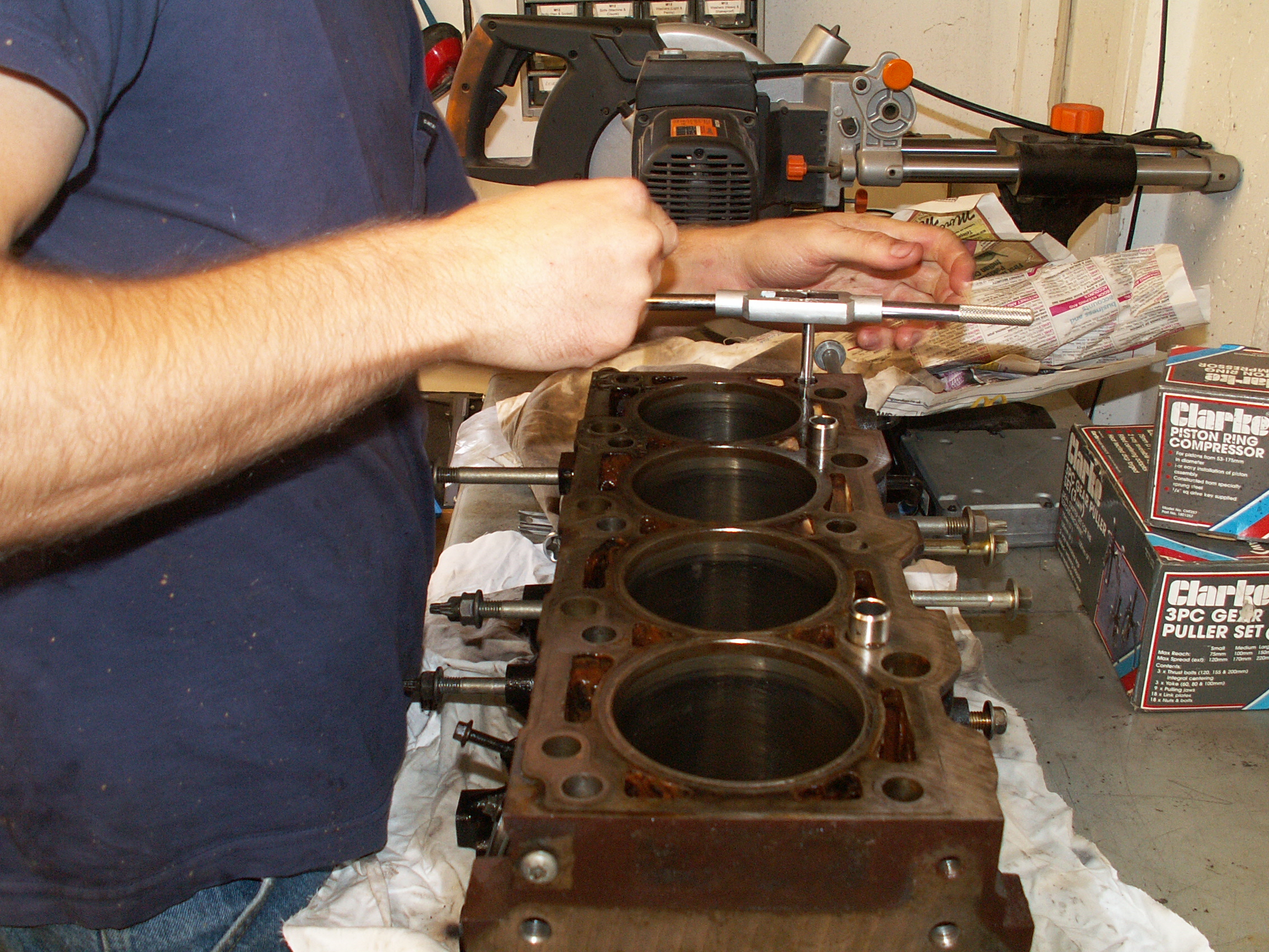
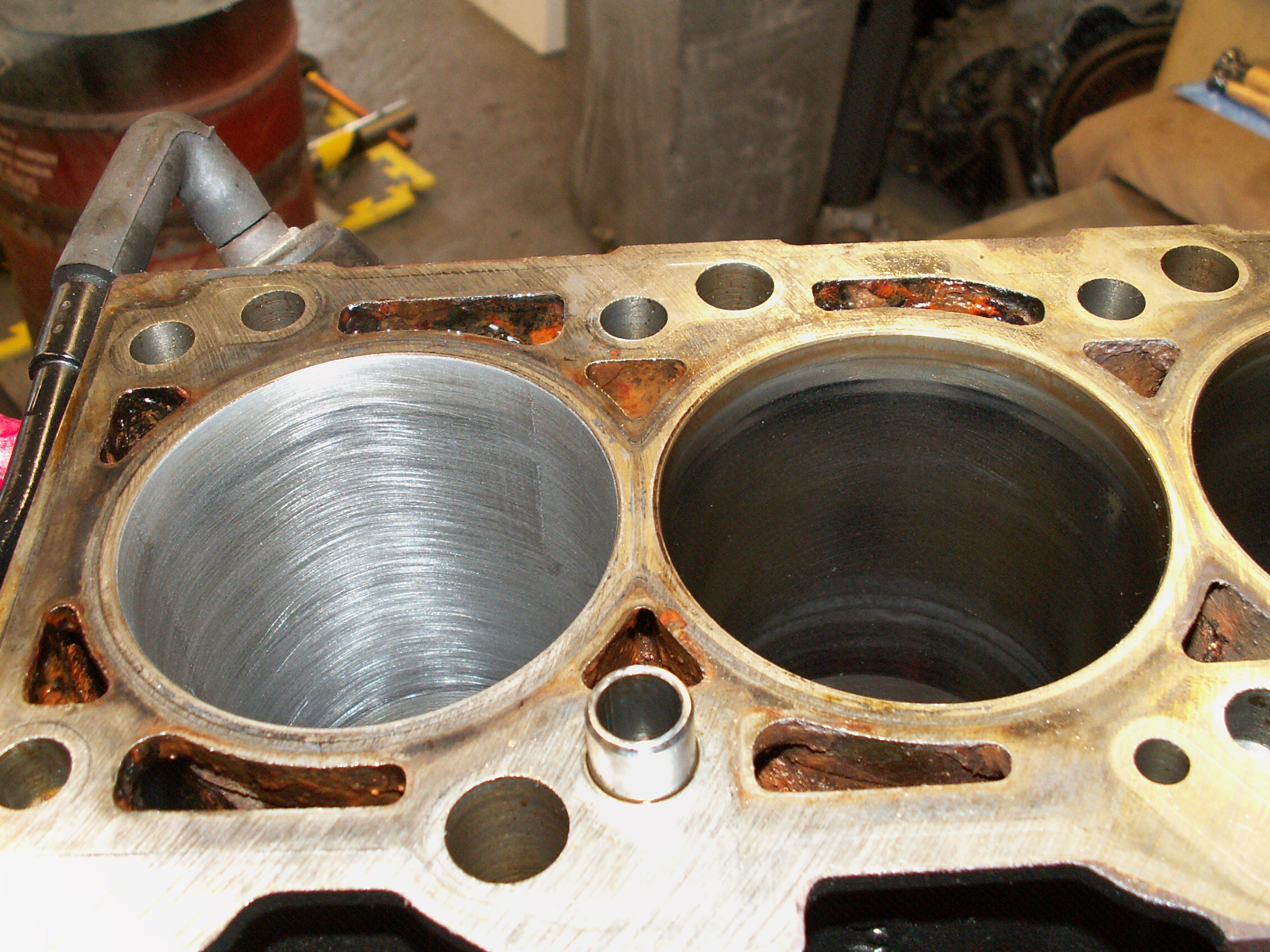
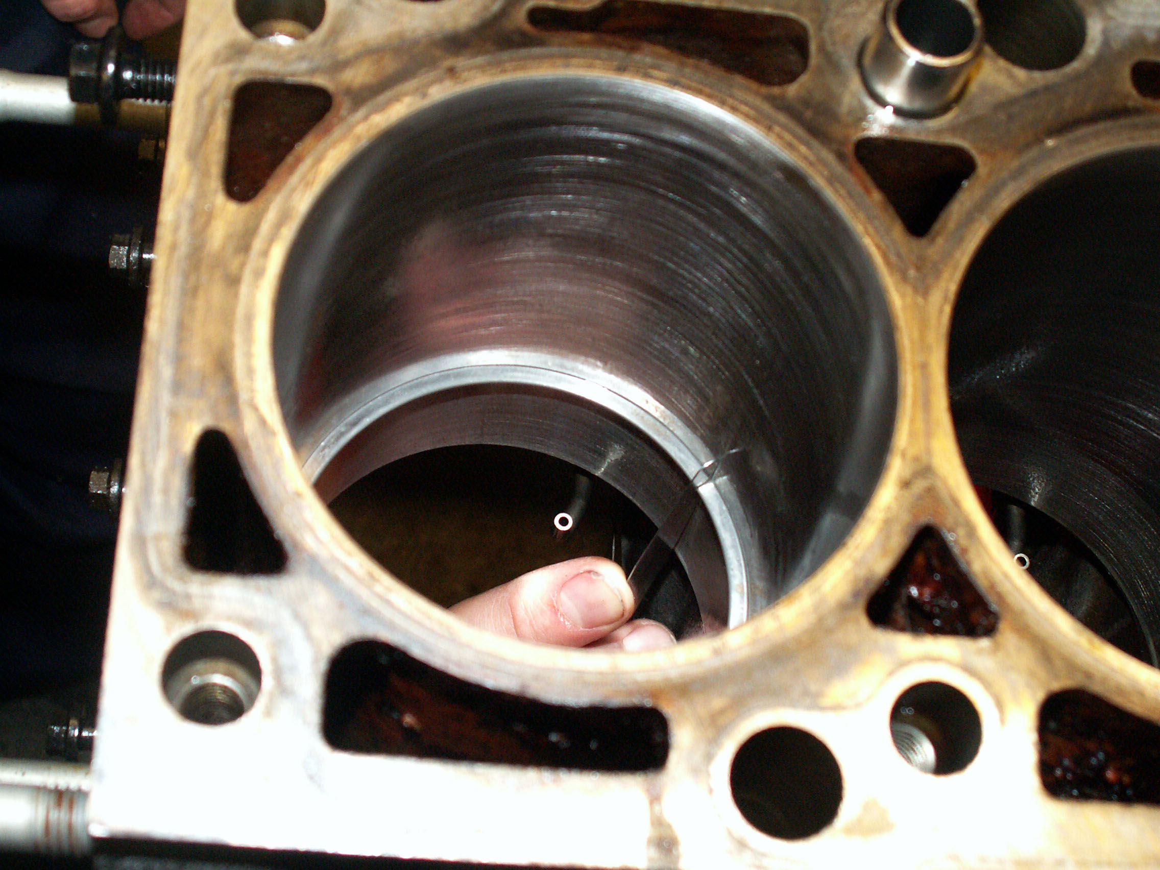
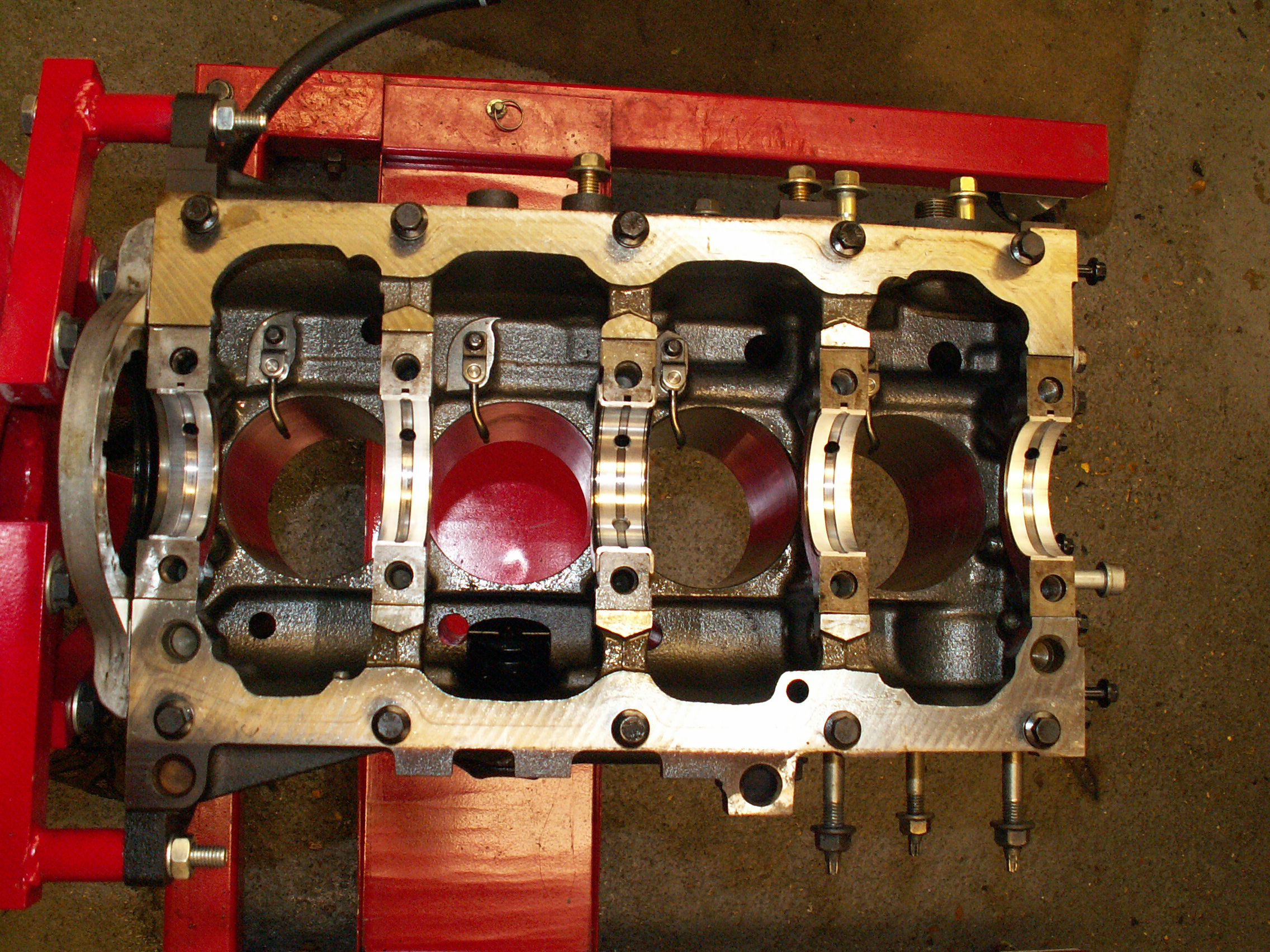
A three-legged glaze breaker was used to restore the cylinder bores by breaking the glaze left by the old piston rings. The cylinder on the left has been restored and clearly shows bare metal with the characteristic cross-hatch pattern left by the oscillatory motion of the glaze breaker. The remaining cylinder bores were cleaned and the residue removed with soapy water. The block was dried and the machined surfaces coated with oil to prevent corrosion.
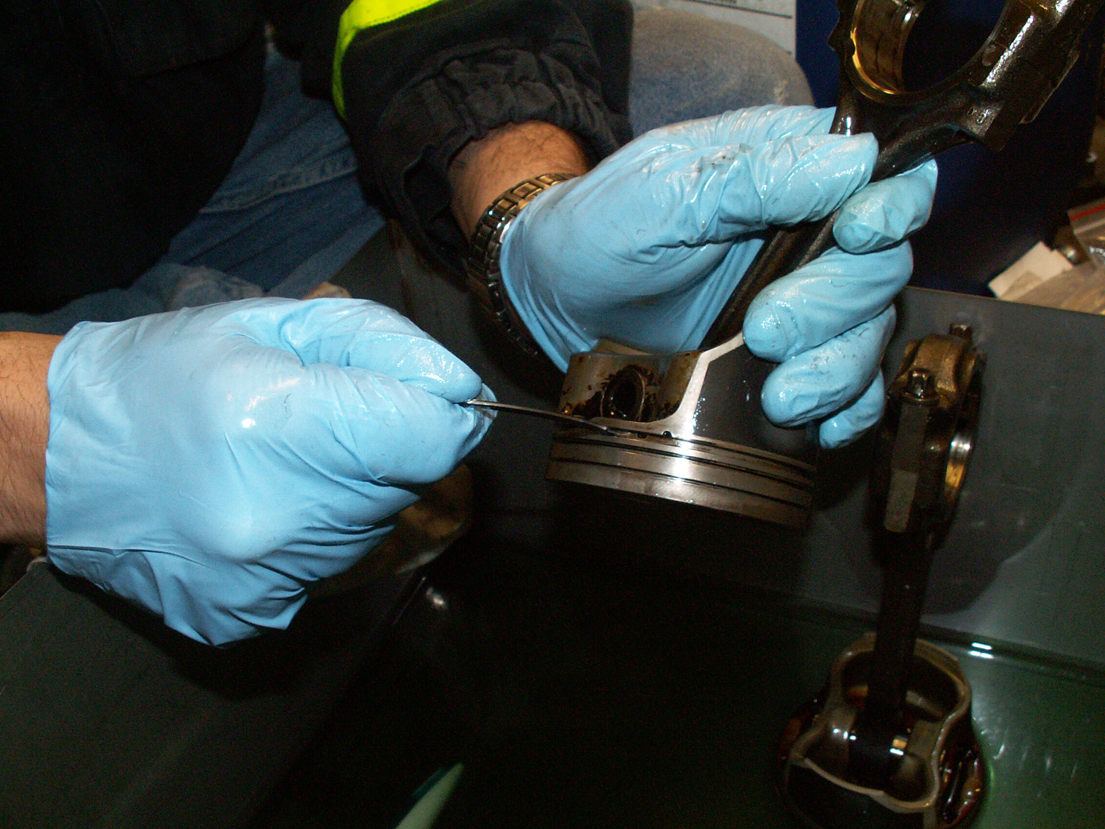
Next to clean were the pistons, in particular the ring channels which were quite heavily coked up. A broken piston ring makes a good cleaning tool as it is ideally-suited to the slot to be cleaned. Paraffin helps to lubricate the ring and prevent it from digging in to the soft piston material. Wire wool was used to remove coke from the flat surfaces but care had to be taken to ensure all the steel swarf was removed.
Here are the cleaned pistons. A few marks remained but they were otherwise free from scratches or pitting so they will be reused.

The cylinder and piston diameters were measured before rebuilding to check for wear and roundness. The bearing caps were inserted and tightened to the correct torque and the two perpendicular measurements taken with a telescopic bore gauge each at the wear ridge, middle and bottom of the cylinder.
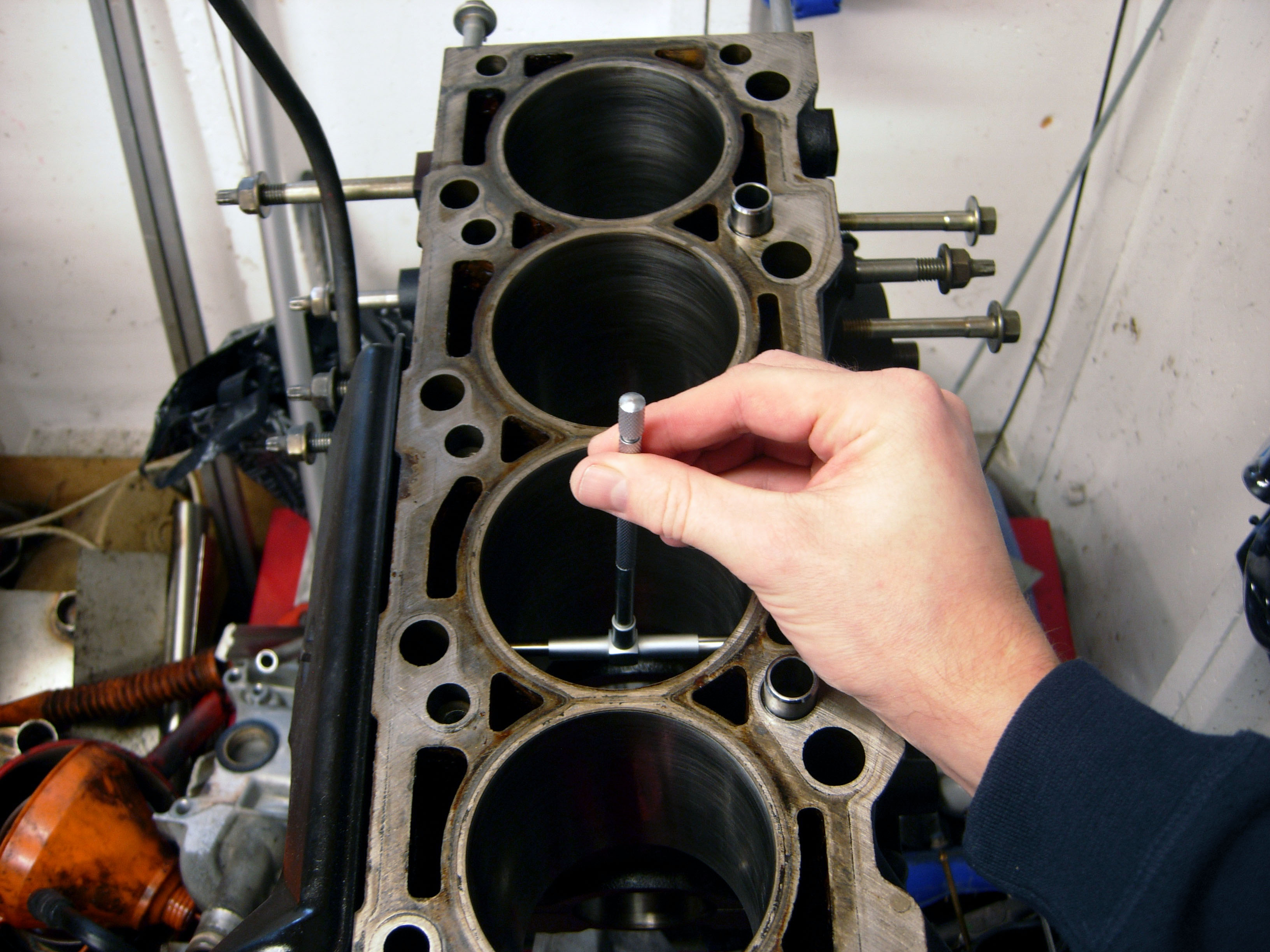
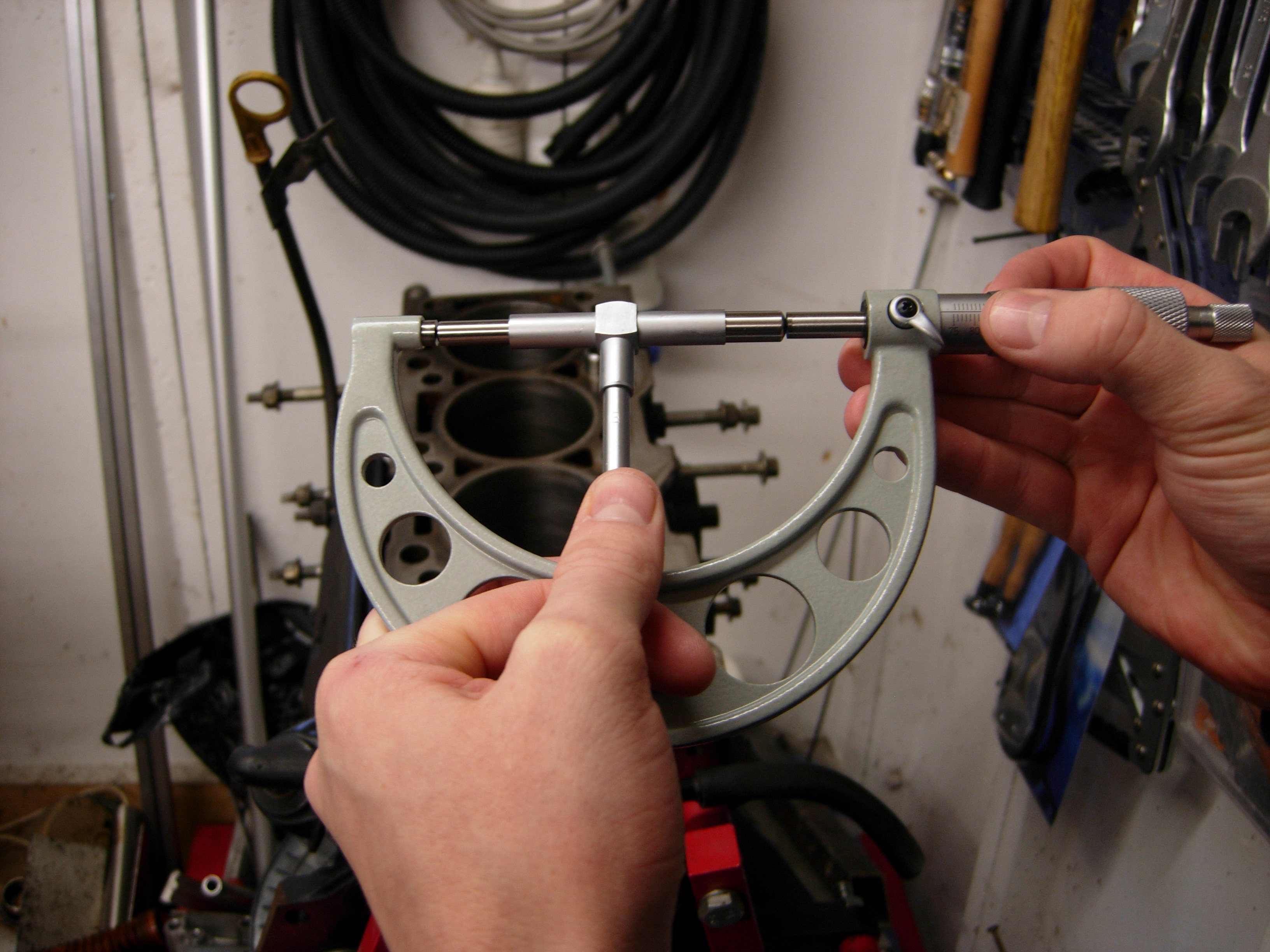
The gauge can then be locked off and measured with a micrometer.
The piston diameter is measured perpendicular to the gudgeon pins just above the base of the skirt. All the measurements were within the limits specified by the workshop manual.

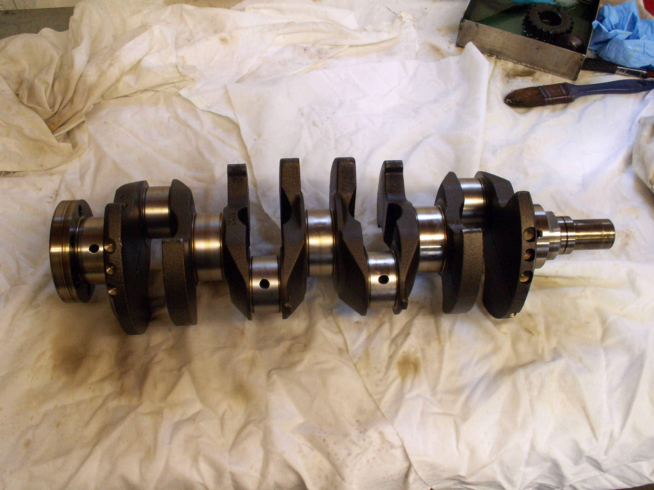
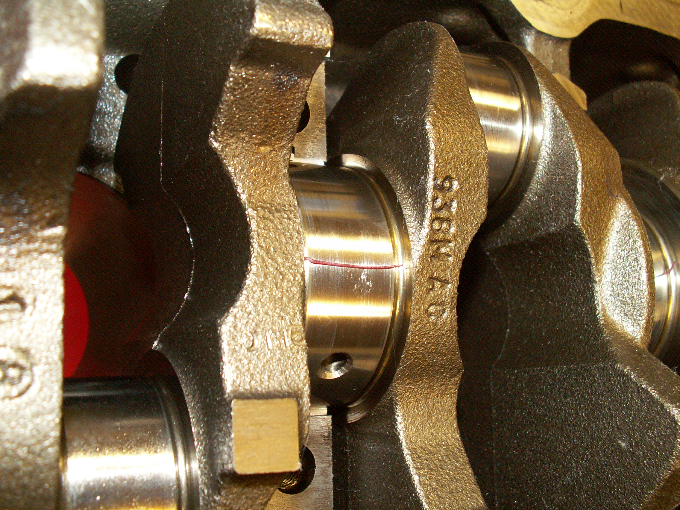
The crankshaft was then cleaned with paraffin. The finish on the journals was checked by rubbing a penny on the journal surface parallel to the shaft; the fact that it did not pick up any material suggested that the finish was OK to start the rebuild. The journal diameters were checked at perpendicular points to ensure they were within tolerance and not out-of-round.
Before fitting the crankshaft and pistons, the piston ring clearance was checked as a belt-and-braces measure to ensure the bore diameter and new piston rings were correct.
The crankshaft's main journal-to-bearing clearance to be checked before fully fitting the crankshaft. Again this was somewhat a belt-and-braces approach since new bearings were being fitted and the main journal diameters were known to be within tolerance. The bearing seats were carefully cleaned before seating the block-side crankshaft bearing shells without coating them with oil. These differ from the shells in the bearing cap as they have a hole to allow engine oil to pass.
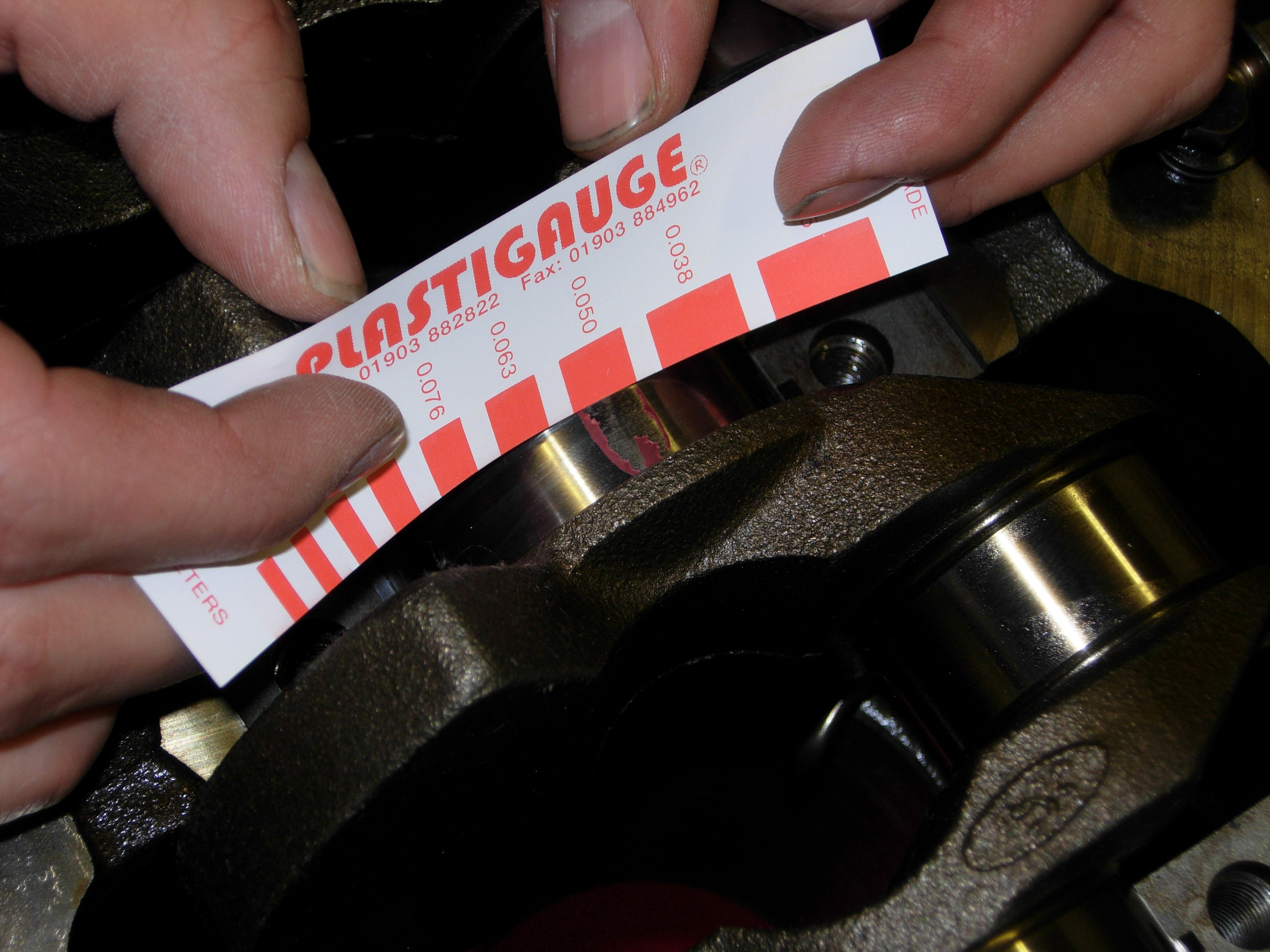
The crankshaft was then put in position and a suitably-sized length of Plastigauge placed on top that would be crushed when the bearing cap was tightened.
After tightening the main bearing caps to the correct torque, they were subsequently removed and the crushed Plastigauge was measured; all were within tolerance so the Plastigauge residue was cleaned off, the bearings lubricated with clean engine oil and the main bearing caps replaced and tightened.
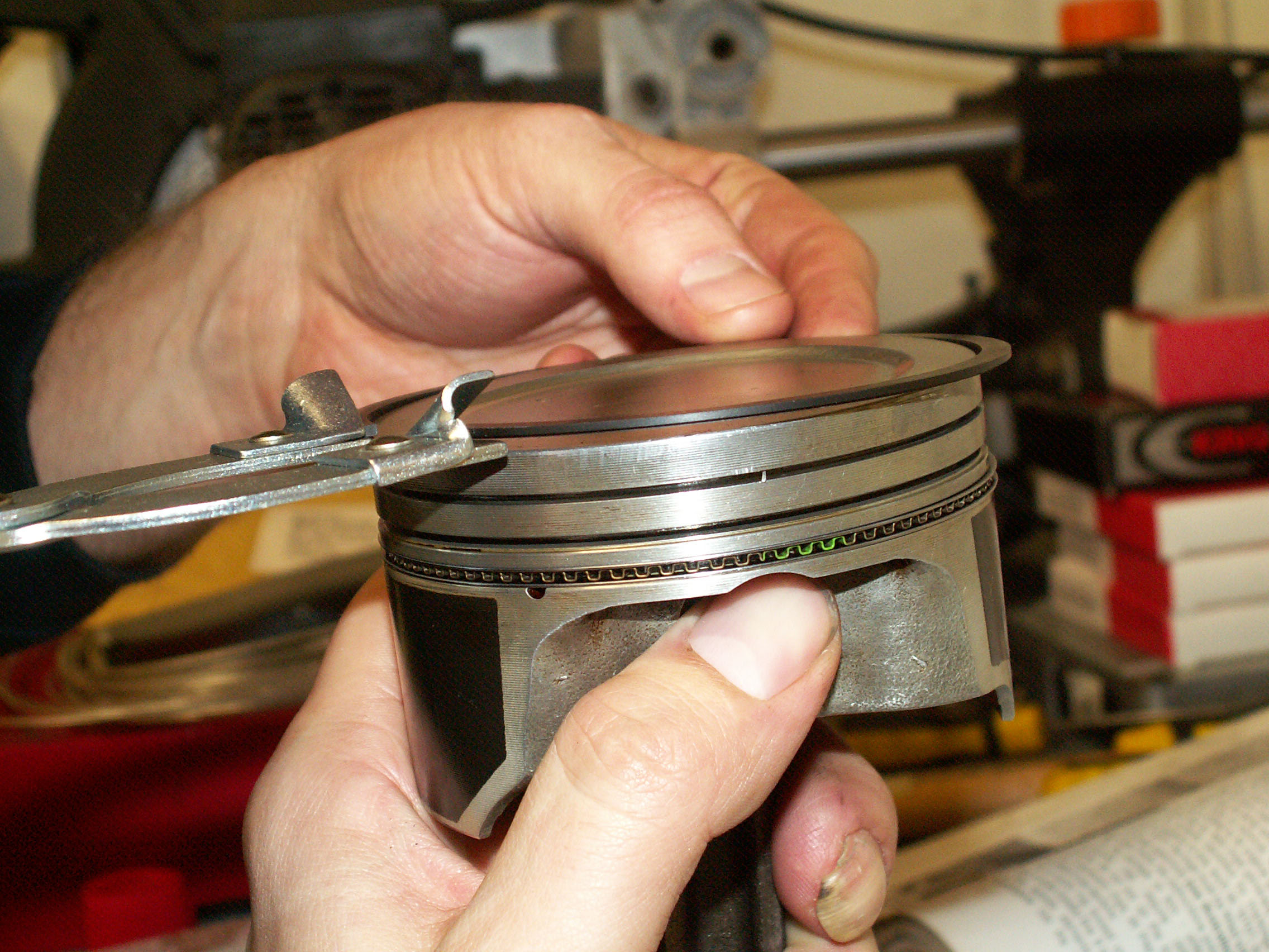
With the crankshaft in place it was time to fit the new piston rings, starting with the oil rings and working upwards. Care was taken to ensure the oil rings butted together without overlapping, that the rings were fitted the correct way up (text facing upwards) and that the gaps were placed approximately 120° apart.
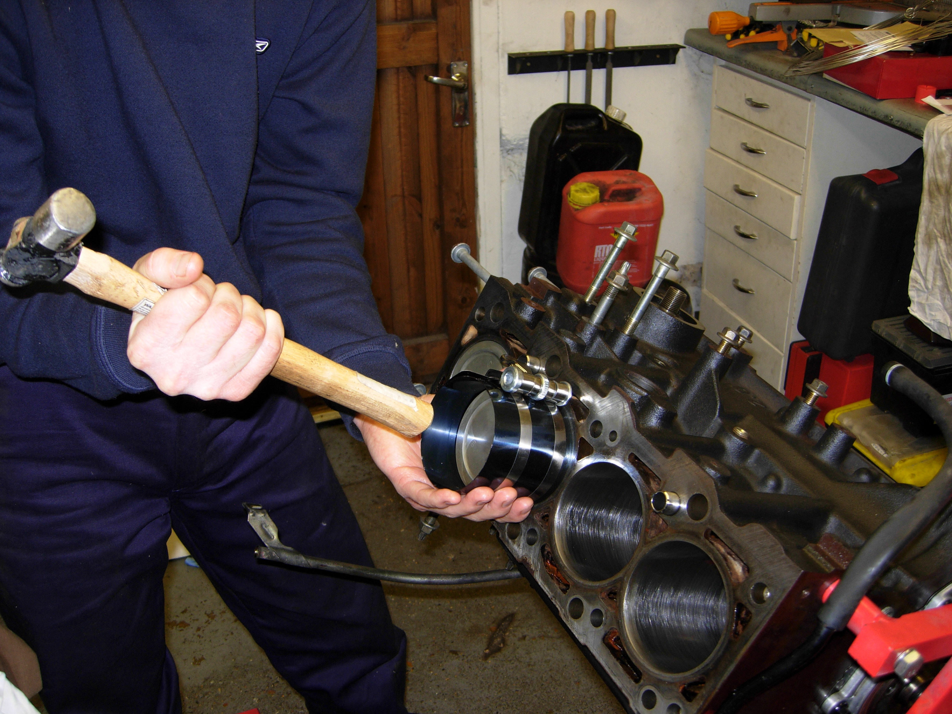
Once the new rings were in place, the big-end bearing shells were dry-fitted to the connecting rod and big-end bearing caps. This was to allow the big-end journal-to-bearing clearance to be measured in much the same way as with the main journals. A piston ring compressor was fitted the piston crown, taking care not to allow the piston rings to rotate out of position as it was tightened.
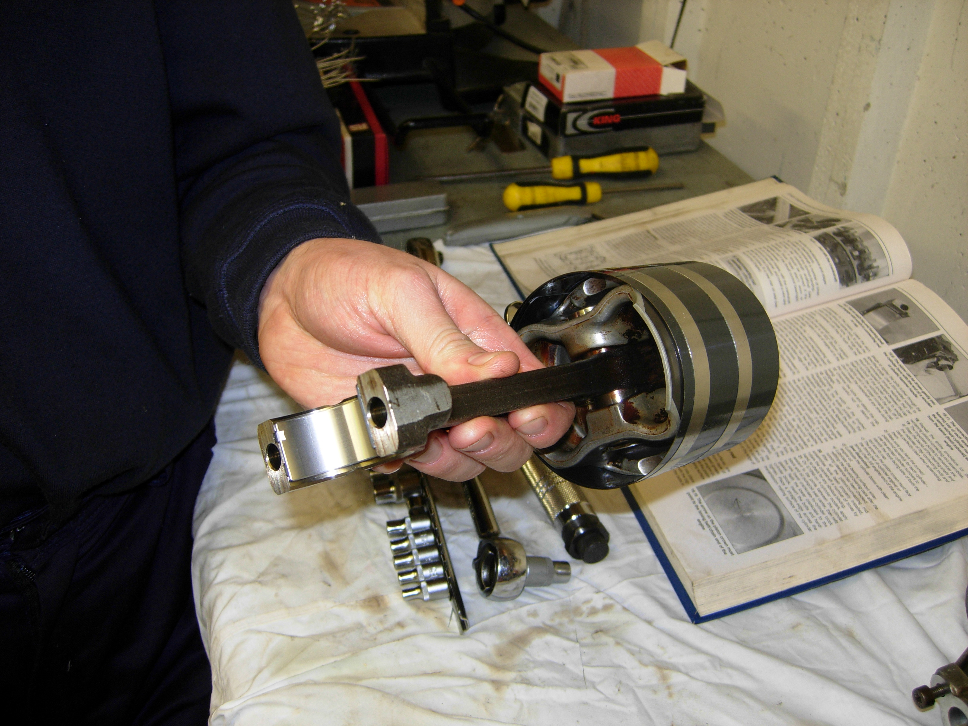
Each piston was then inserted into its respective bore. The wooden end of a hammer was used to square up the piston ring with the face of the block then gently tap the piston into its cylinder. The journal-to-bearing clearances came in within tolerance so the bearings were cleaned and oiled and the caps tightened.
The crankshaft was turned a few times to feel for binding. A small amount of roughness was felt due to the newly-deglazed cylinders but this will reduce as a new glaze is made. With the pistons in place and the big end bearing caps tightened, the oil pump was next to install. A ruler was used to ensure that the pump lay parallel to the block before installing the new gasket. The pump was primed by pouring in fresh engine oil, however the majority leaked straight through but at least it was well-lubricated.
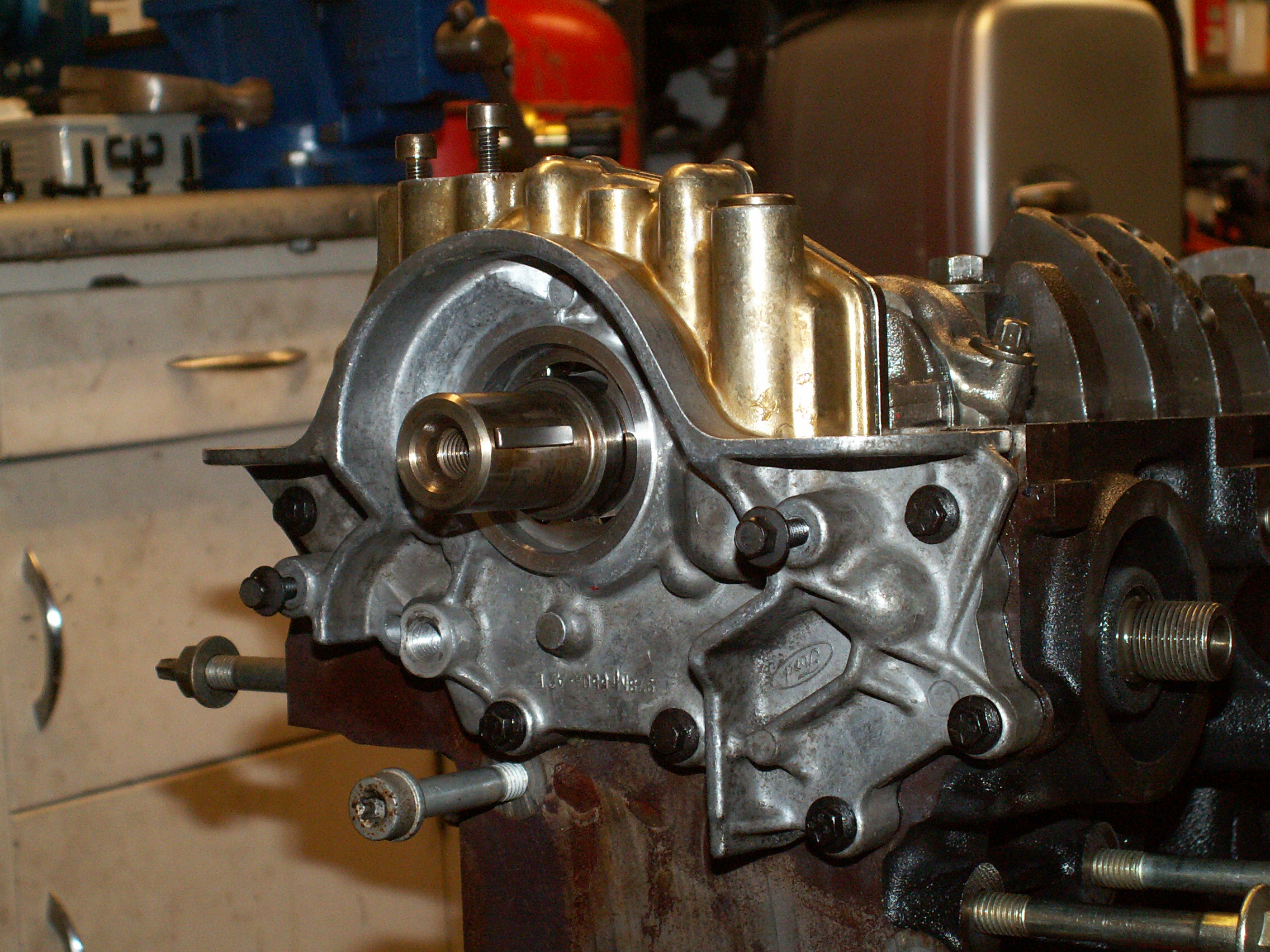
The lower crankcase bolted straight on. Ford doesn't supply a gasket for the sump so a 3mm bead of copper-impregnated silicone instant gasket was laid down on the mating surfaces.

The sump was attached, the block lifted to the ground and rotated so that it sat on the sump. The new head gasket was then laid into position, taking care to ensure that the mating surfaces were free from dirt.
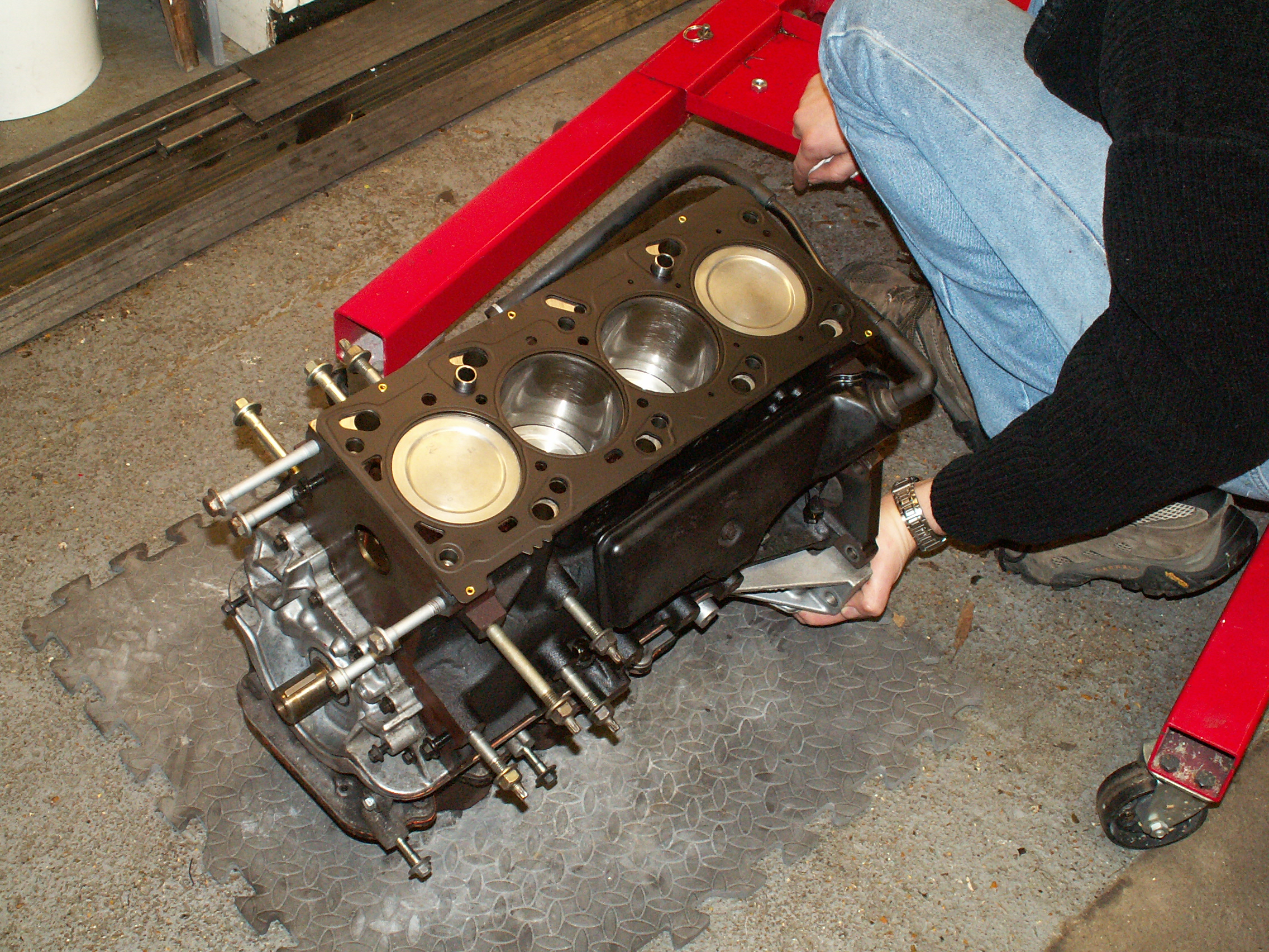
The cylinder head was refitted and the bolts tightened in the sequence specified by the workshop manual. Before inserting the bolts, the threaded holes were blown out with compressed air to remove any oil or dirt that would have become compressed when the bolts were tightened.
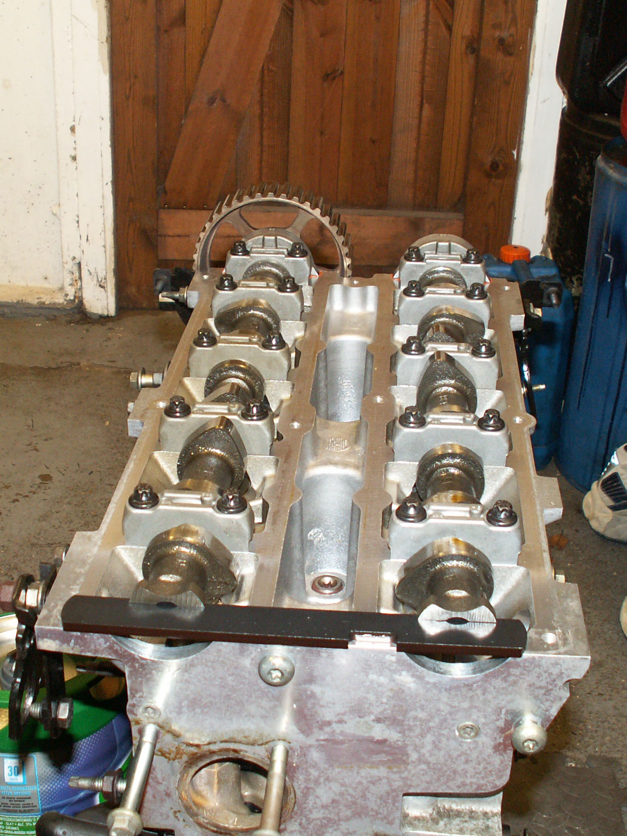
The tappets were refitted having liberally coated them with engine oil. Before fitting the camshafts, the engine was cranked to approximately 2 cm before TDC to ensure that the valves, which had not yet been timed, didn't foul any pistons. The task of tightening up the bearing caps is quite monotonous as even pressure must be applied to the camshaft during tightening. The camshafts were rotated with a spanner and the camshaft setting tool inserted into the grooves to keep them correctly aligned.

© 2010 M. R. P. Thomas