Mark Thomas's Website
Current: /Other/Workshop/Turner's Cube

Menu:
Turner's Cube
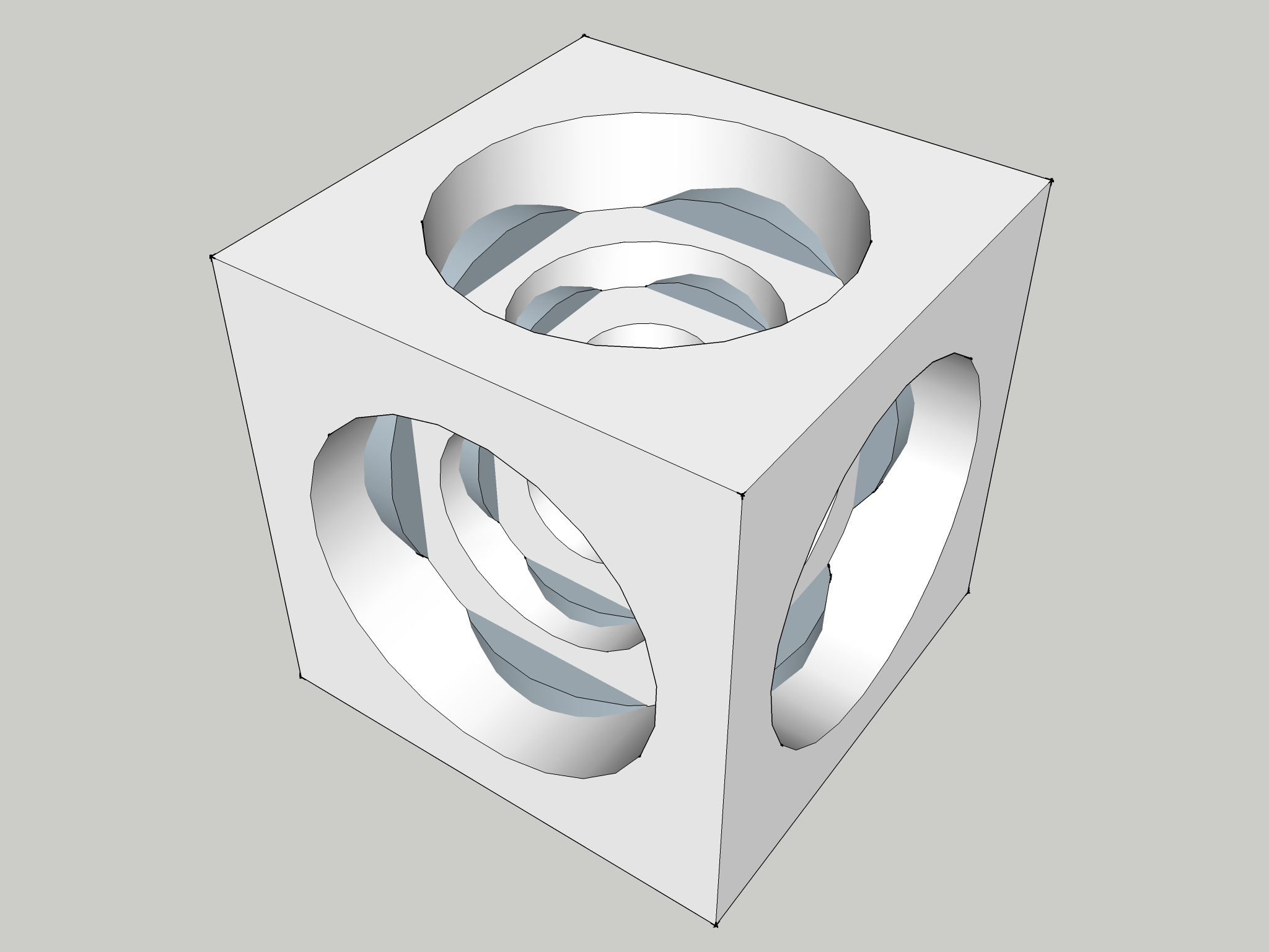
The Turner's Cube is a cube whose faces have been carefully bored to reveal a cube within it. The process can then be repeated to reveal more cubes. This Google Sketchup drawing gives a better idea than any description:
I first saw one in Germany on the desk of an academic whom had been given one by a colleague. It so intrigued me that I hoped I'd one day have the skill and tools to make one myself.
Normally a Turner's Cube would be turned on a lathe (hence the name), held by a four-jaw chuck. This page on CNC Cookbook gives a nice example of using CNC to automate some of the repetitive operations required to fabricate one of these things. It also contains example dimensions and an Excel spreadsheet for calculating them. Being that I don't own a lathe and haven't yet converted my mill to CNC, I used a rotary table to make the bores on mine. In the spirit of not doing things the normal way, I used perspex and not aluminium in the hope that it would give a more pleasing result.
Squaring Up the Cube
I was very fortunate to be given a slab of 3" perspex by a friend in an engineering workshop which would have been prohibitively expensive to buy myself. Having been roughly cut by a bandsaw, it needed machining to size with my home-made fly cutter.
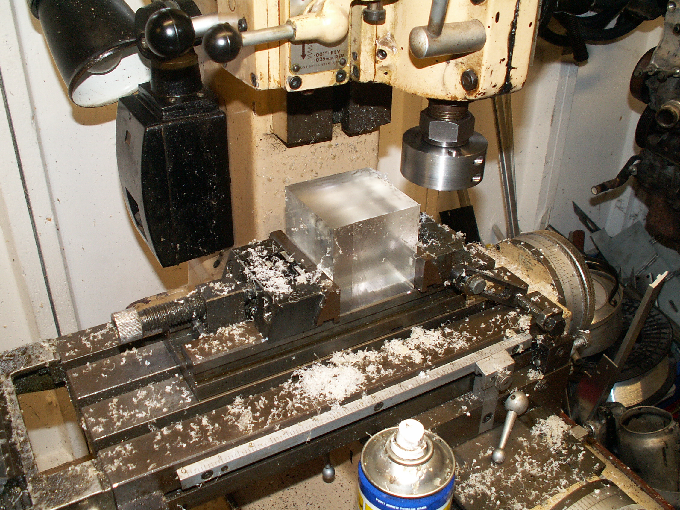
The two uncut edges were placed in the jaws of the vice with which one face was machined flat and perpendicular to the uncut edges. The cube was then rotated 180° about the horizontal such that the opposing face could be machined, giving four flat and perpendicular faces. In order to ensure that the fifth face was perpendicular to the already-machined faces, the cube was left in place and machined with the side of an endmill:
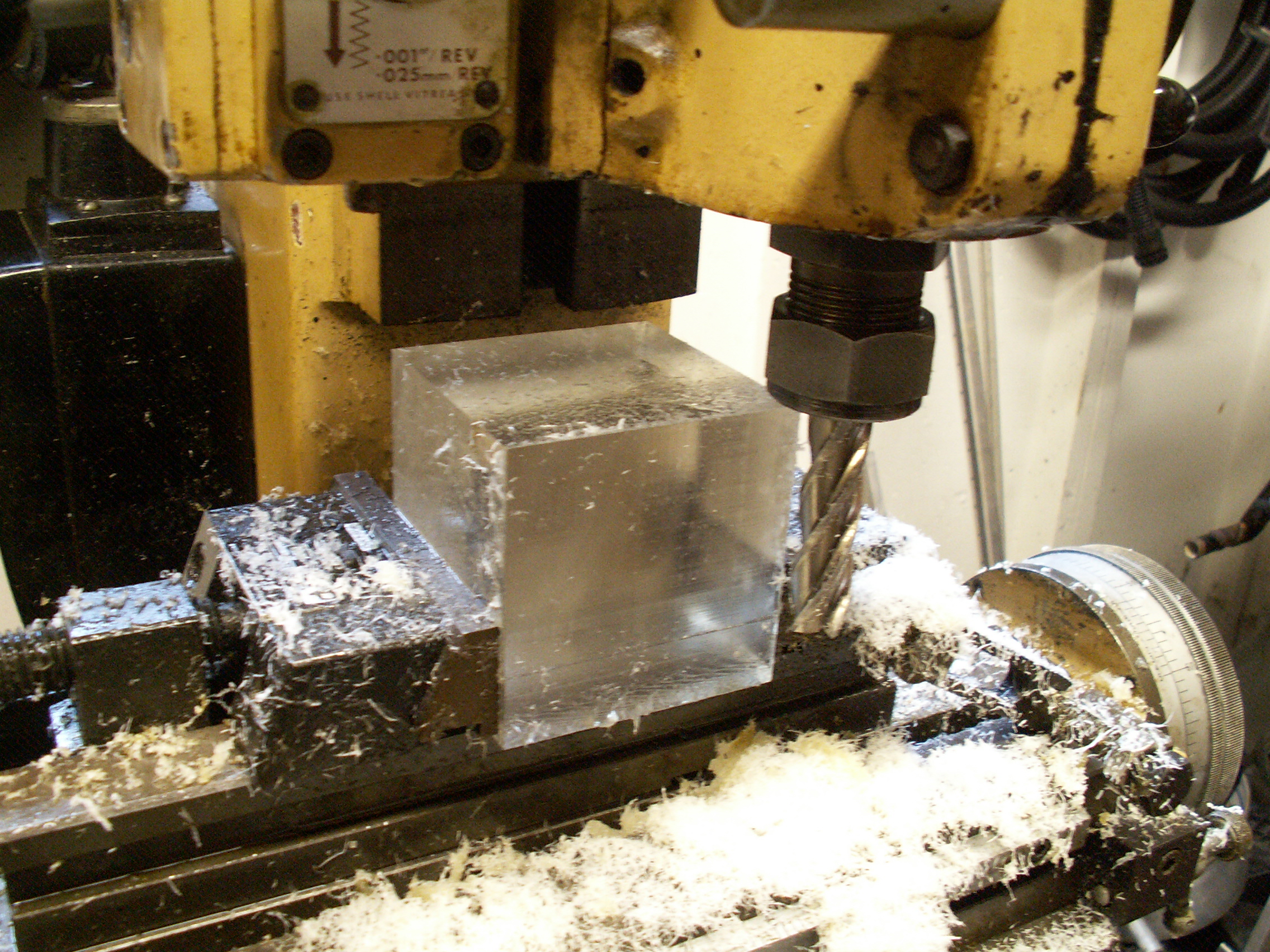
Although my longest endmill was shorter than the width of the cube, a sufficiently large step could be milled that could be placed flat on the bottom of the vice, allowing the sixth face to be machined. The fifth face could finally be machined flat so that all edges were flat and perpendicular but not of equal proportions. Further machining operations could be made in the knowledge that the all faces would remain perpendicular to one another.
Later steps left the final cube dimensions reduced from 3" to 2.89" to remove damage on the cast edges. Although I was brought up in the UK with metric units, I continue to work with Imperial units due to the calibration of my milling machine.
Alignment Holes
The holes that pass through the centre of the final cube also served as alignment holes by passing a 1/4" rod through the axis of the cube to the centre of rotation of the rotary table. I polished the cube (see Polishing) before continuing as it's much easier to polish a flat surface than a faceted one. The holes were reamed to size to make as them as smooth and cylindrical as possible. The holes were drilled to a depth of about 1.5" to allow the three opposite bores to be made. Ideally they would have penetrated the whole length of the cube but my smaller drill bits weren't long enough.
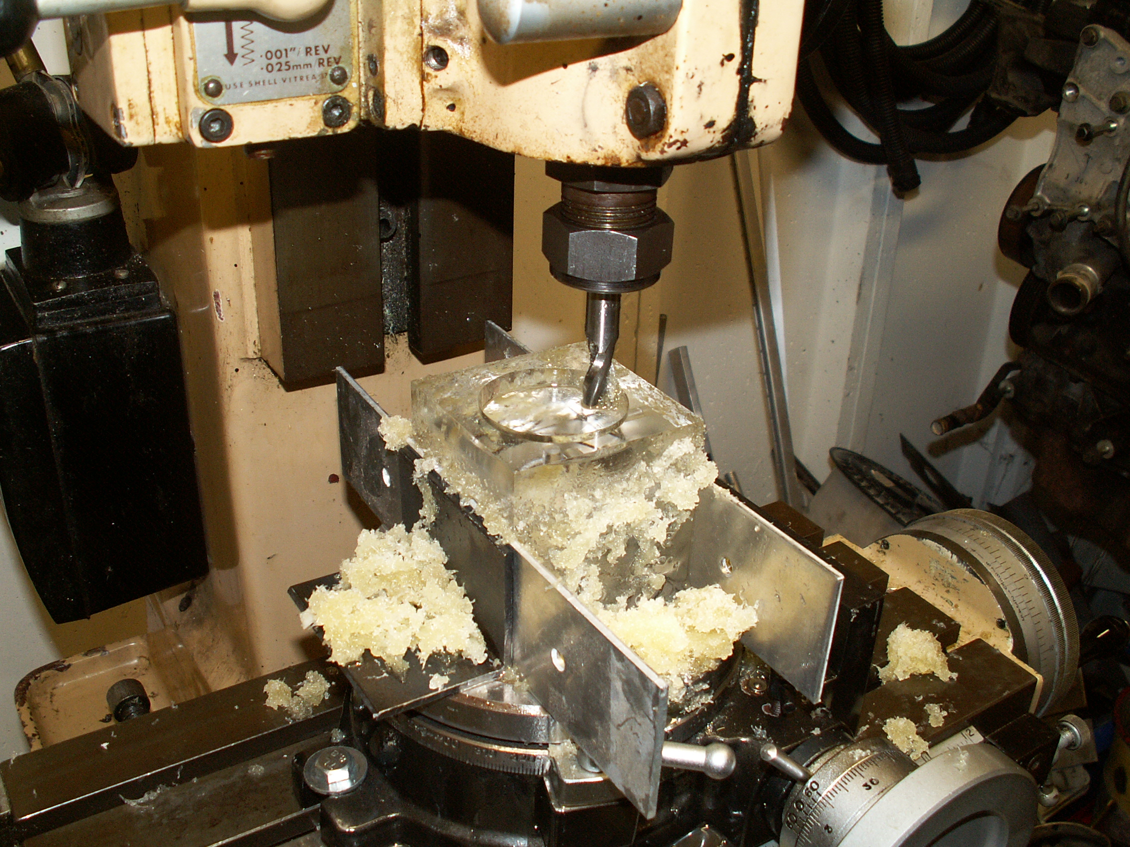
Three Outer Bores
With the rod aligning the cube and rotary table, I made a crude soft vice from a pair of steel angles and plates of aluminium. The X-Y table was aligned so that the centre of the milling cutter passed through the centre of rotation of the table, with the Y-axis locked off. The cutter was a 1/2" two-flute HSS slot drill which was plunged 33 thou at a time, requiring three concentric passes to get the bore to size by increasing the X-deflection on each rotation. Using neat cutting oil as a lubricant and coolant, a surprisingly good finish could be produced.
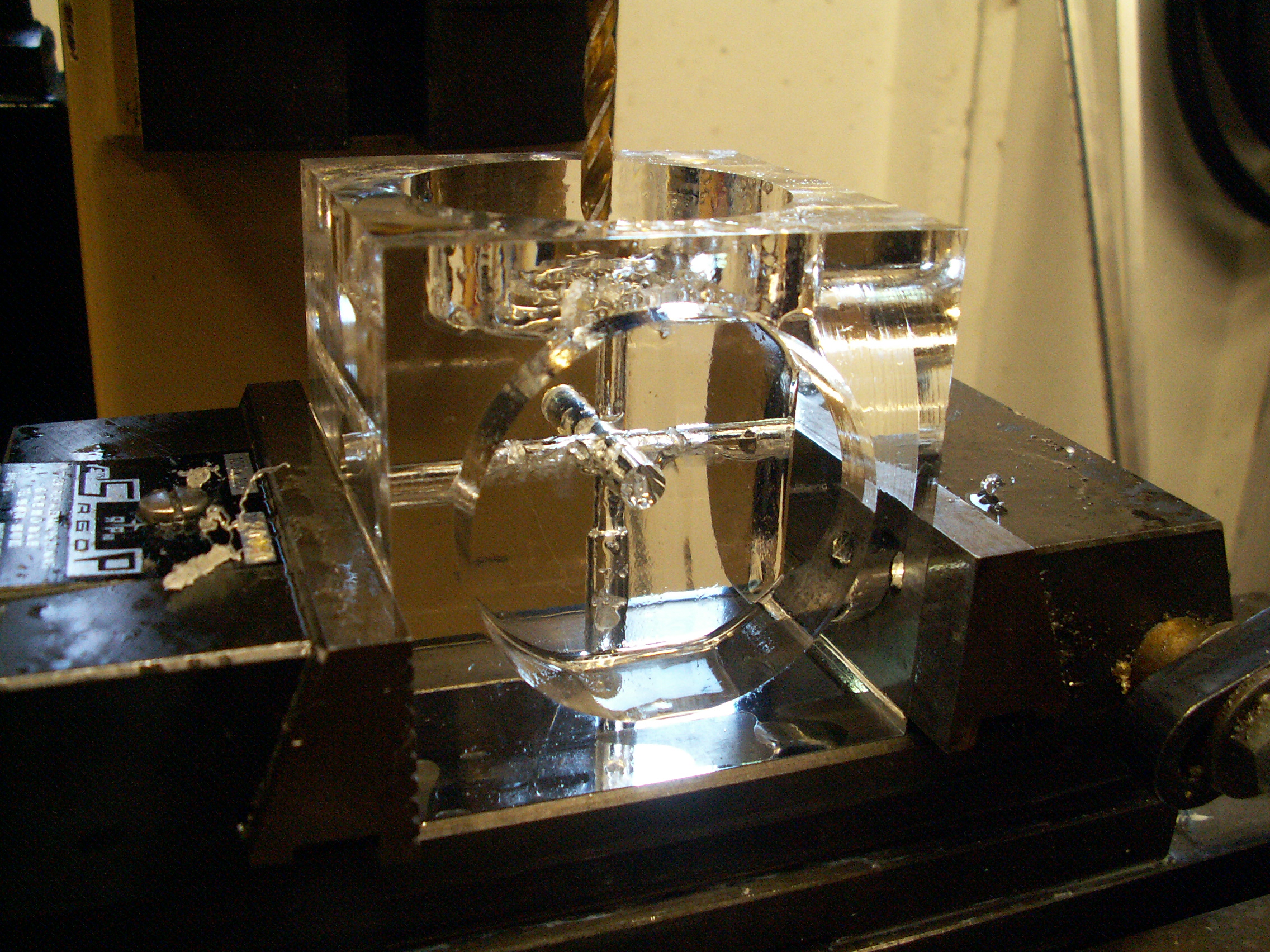
Lengthening the Alignment Holes
With the first three outer bores made and polished, the edges of the first cube began to reveal themselves. The alignment holes could now be lengthened by drilling from the opposite side. It was critical that the original cube be made exactly to size for this operation to work, as an edge finder can accurately find an edge but the centre can only be found by moving the axis half the width of the cube. Fortunately they aligned exactly and were reamed to make a seeminly continuous hole.
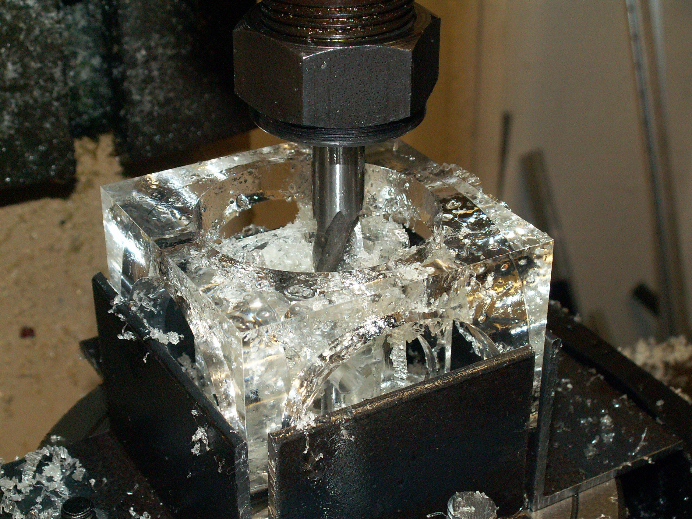
Subsequent Boring Stages
Everything was now in place to finish the boring operations. Each of the three bores were made one at a time rather than completing all the bores for each face in one go. Although this was a lengthy approach, it allowed for more errors to be repaired should they arise, not that they did. I was concerned about the amount of movement of the cube with the two-jaw vice so I made a 4-jaw one with an additional pair of angles that were machined flat to relinquish the need for aluminium.
Polishing
The fly-cut faces were acceptably good after a quick cut with automotive polish. However, the bores displayed distinct circular machining marks on the bottom and shallow continuous lines on the sides. Had I used a boring head or a lathe then this should have been markedly reduced as single-point cutting tools usually yield a better finish.
I first removed all machining marks with P1500 silicon carbide (wet-and-dry) paper. This removed any lustre but gave a good, flat base for subsequent polishing. The abrasive scratches were removed with an automotive rubbing compound (Farecla G3 fluid) and brought to a deep lustre with automotive polish (Autoglym Super Resin Polish). Following a few hours' polishing with a yellow cloth in front of the TV, the Turner's Cube was complete.
Industrial perspex polishes may have yielded faster results but I don't believe the final product would have looked any better. From my exploits with automotive refinishing (see my refinishing pages), a good rule for surface preparation and refinishing is not to be scared of using a coarse grit when it is needed; had I skipped the sanding stage on this job then the machining marks would not have been removed but simply brought to a bright lustre.
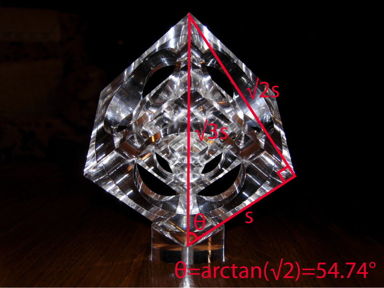
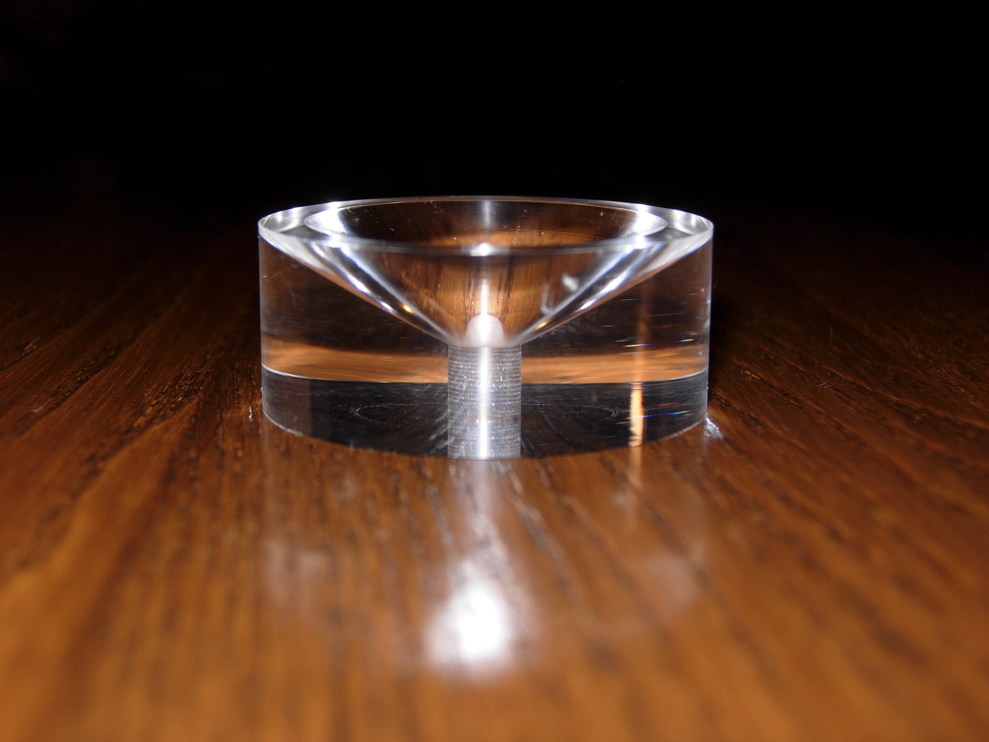
The Base
The cube looks more interesting when supported so that two vertices pass through the vertical, rather than flat on a face. A conical base that touches three edges ensures that it stays upright. The angle of this cone is 2*arctan(sqrt(2))=109.47°, twice the angle between an edge and the diagonal across a face as follows:
The Finished Product
Photographing this to look good was difficult. Experimentation with white backgrounds and strong ambient lighting look OK but it didn't make the cube jump from the screen. Instead a single-point flash placed close to the cube gave a nice dark background while showing the light bouncing around inside.


© 2010 M. R. P. Thomas